Yampad v2 Build Guide
Parts List
Here’s a list of parts needed for the build:
-
1 x Yampad v2 RGB Macropad Keyboard Kit
Kit Includes:
- 1 x Yampad v2 PCBs
- 1 x Yampad v2 Acrylic Bottom Plate
- 1 x Yampad v2 Acrylic Switch Plate
- 18 x SOD-123 Diodes
- 18 x Kailh Hotswap Sockets
- 7 x 7mm Brass Standoffs
- 14 x 6mm Hex Screws
- 1 x .91" OLED Display
- 1 x 6x6 Button
- 4 x Clear Rubber Feet
Not included in the kit but required to complete:
- 1 x Pro Micro Controller
- 18 x Keyboard Switches
- 18 x Keycaps
Build Steps
- Solder Components
- Solder LEDs
- Solder Diodes
- Solder Hotswap Sockets
- Solder Controller & OLED Headers
- Solder Reset Button
- Assemble Case
- Install Stabilisers
- Install Switches
- Connect OLED Display
- Stick on Feet
1. Solder Components
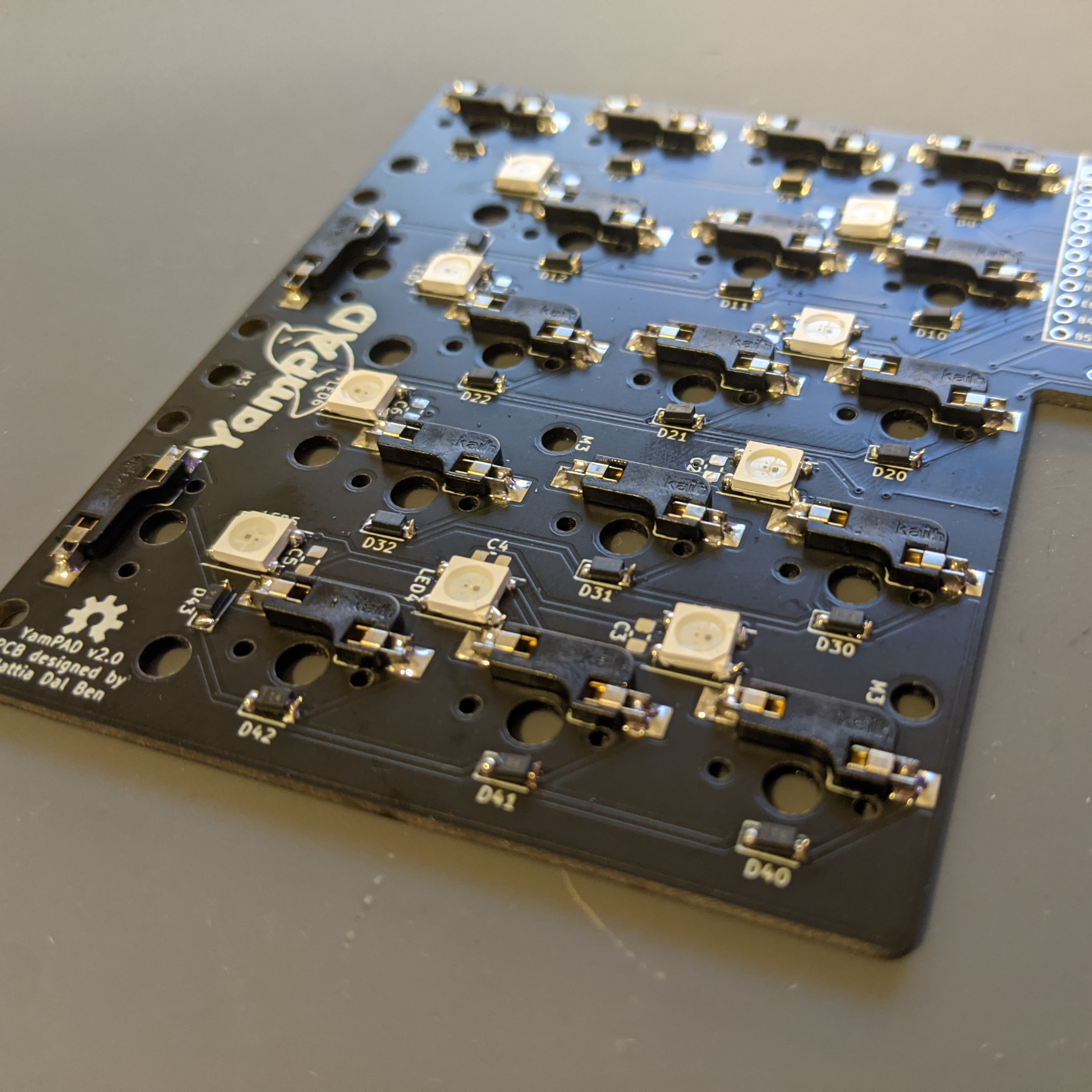
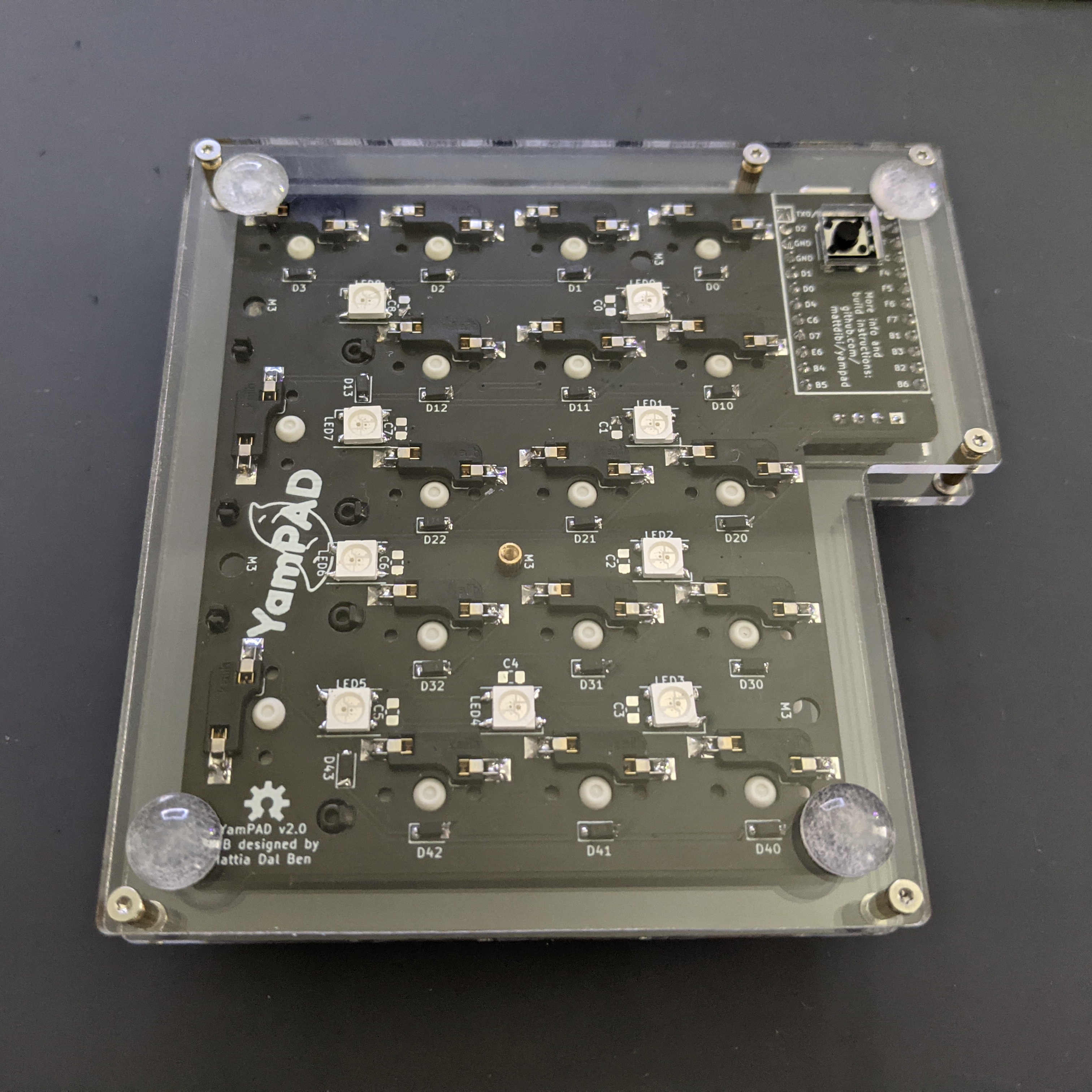
Solder LEDs
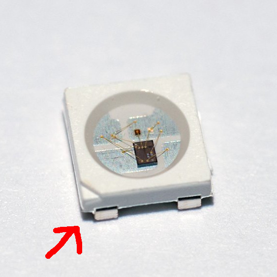
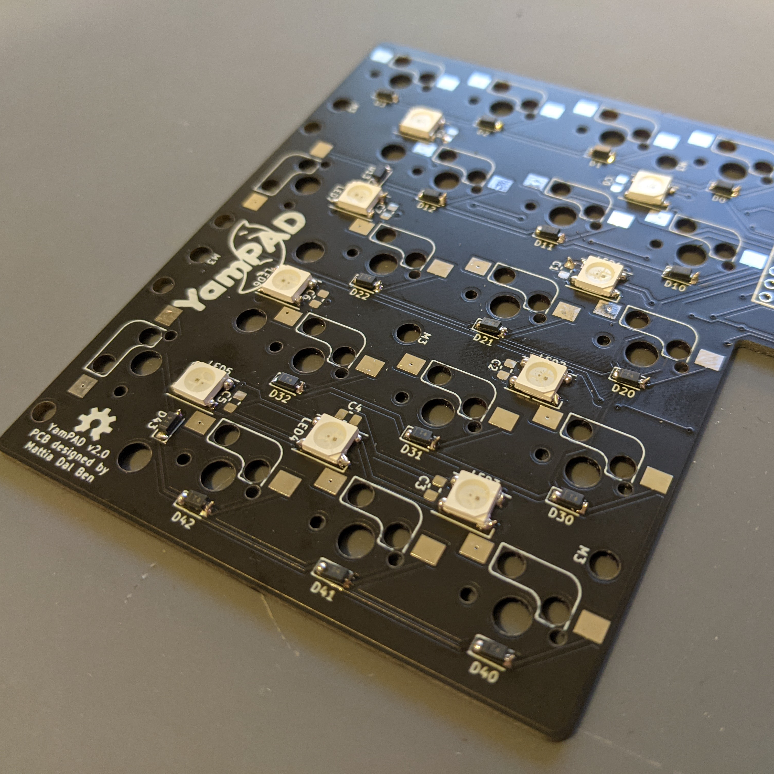
The WS2812B LEDs have one corner different to the other three corners, this odd corner faces towards the marked corner on the silkscreen.
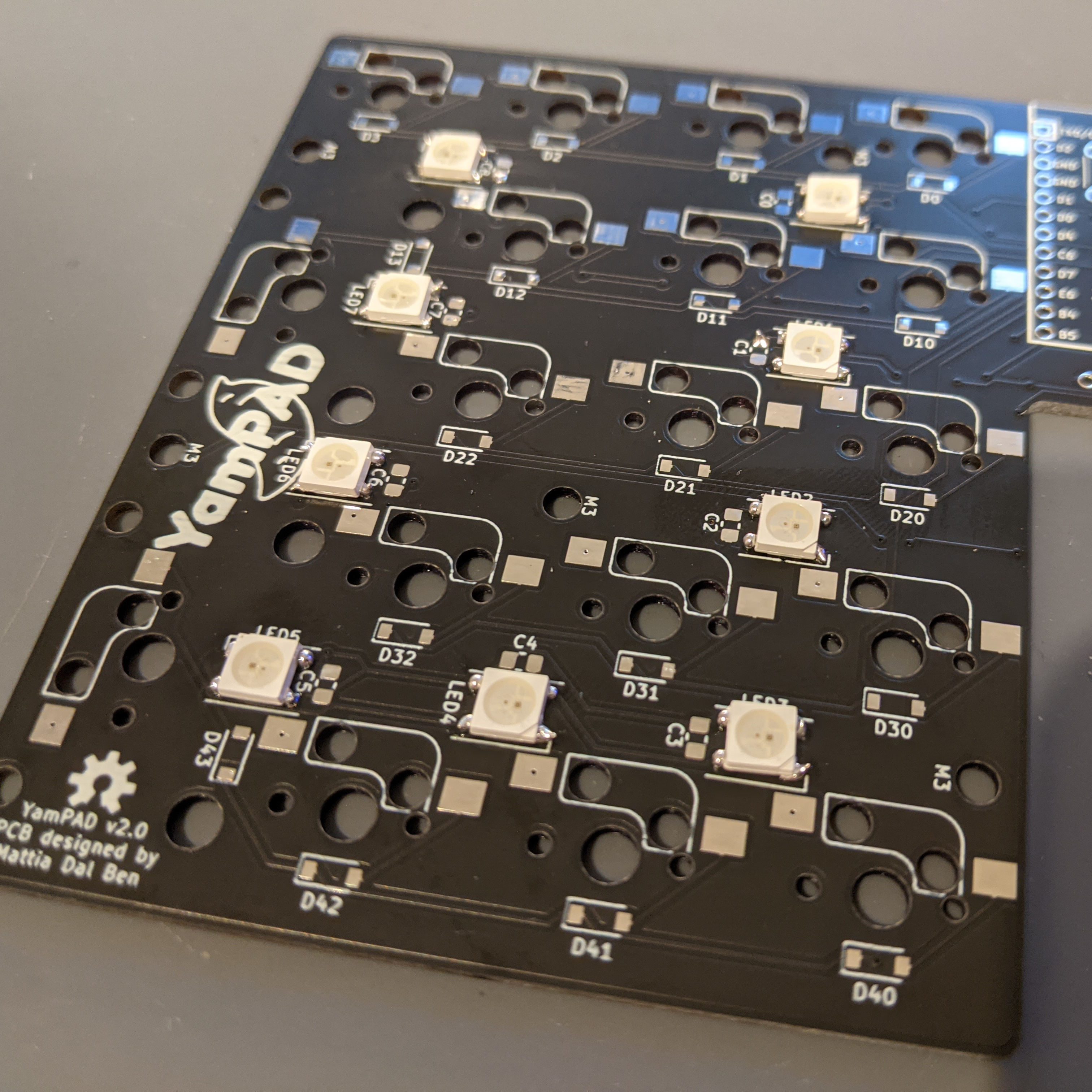
Add a small amount of solder to one of the LED pads for each LED and then heat with your iron and place the LED into place.
Solder the remaining three pads ensuring the solder flows to both the pad on the PCB and the pad on the LED.
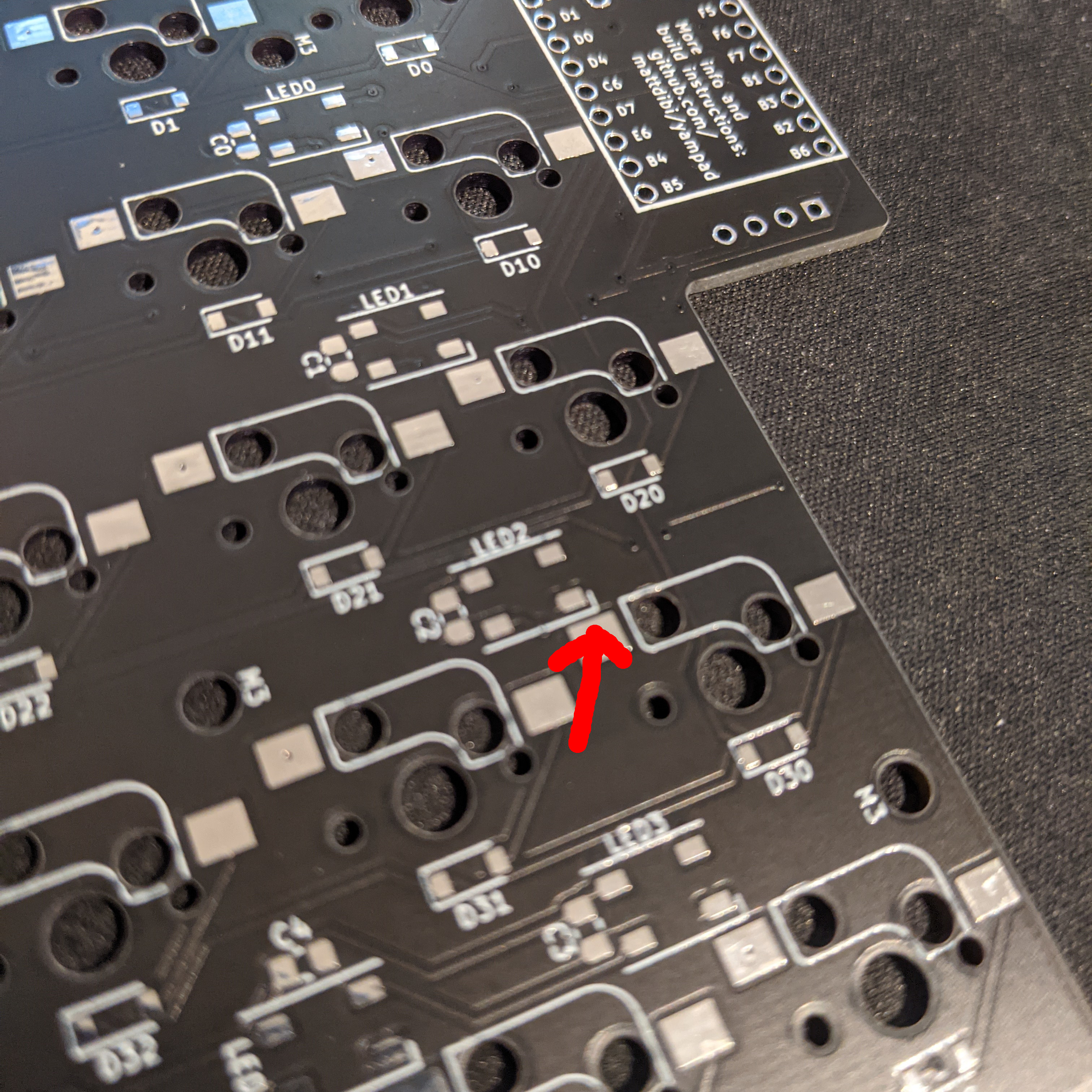
Diodes are directional and the line on the diode faces the direction of the closed end of the silkscreen.
Add a small amount of solder to one pad for each diode and then while heating the solder place a diode into place. Heat and add some solder to the second pad of the diodes.
Place the Kailh hot swap sockets onto the board and while heating each pad, add solder.
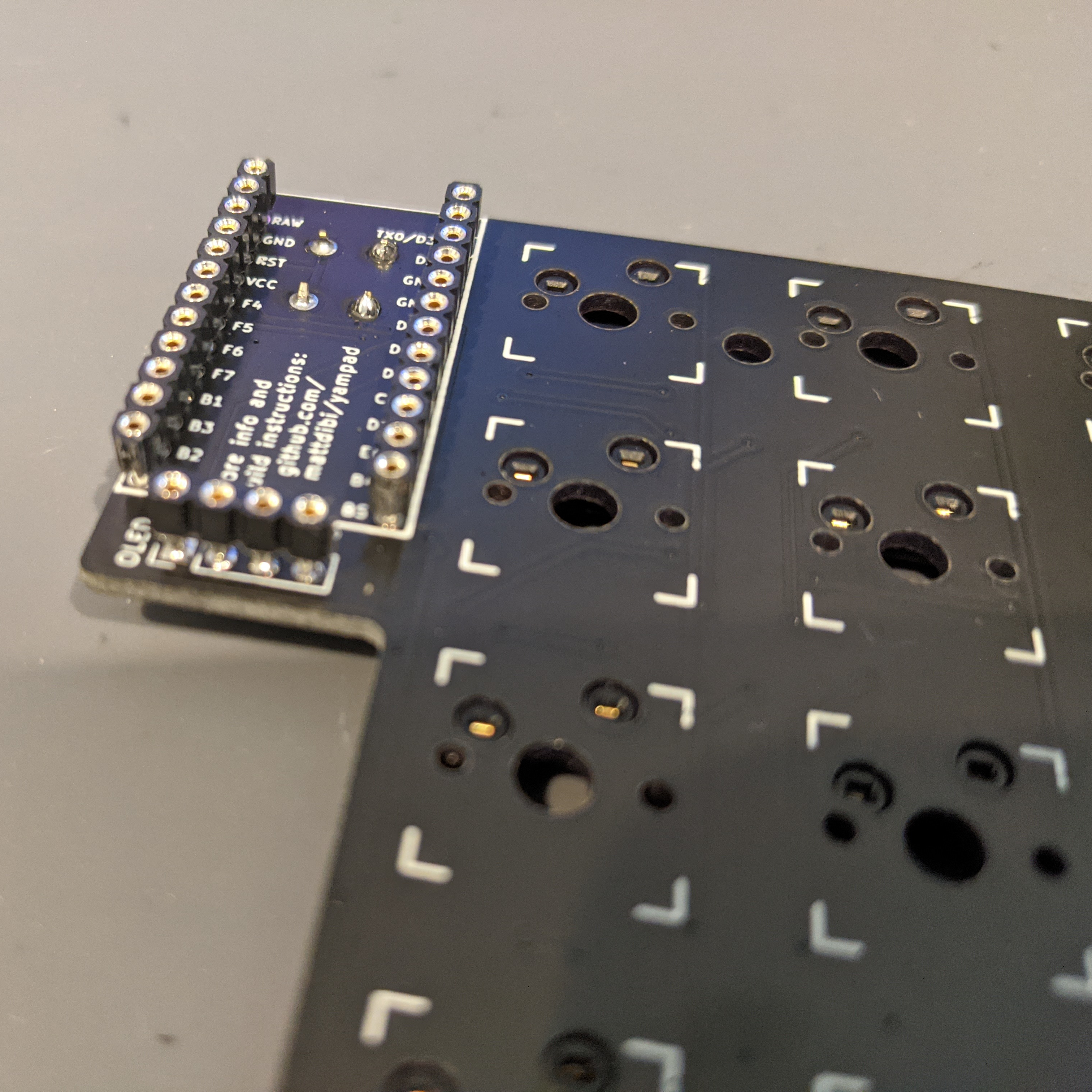
You can skip this step if you want to direct attach the controller and OLED display. The above are Machined Breakable Female Headers and used with Mill-Max Pins allow the controller to be hot swapped (removed, replaced, upgraded etc).
Attach the controller first to the top side of the board and then attach the OLED Display to the board second using the controller as a table for the display to reset evenly on.
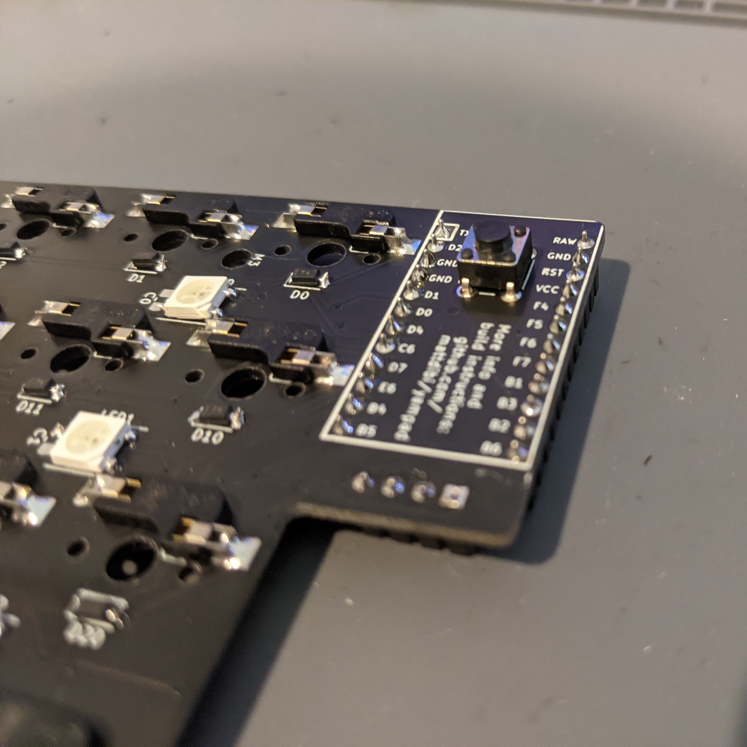
Solder the reset button to the underside of the board.
2. Assemble Case

Remove the protective film from the acrylic plates and attach the brass standoffs using the hex screws to the bottom acrylic plate.
Place the PCB onto the middle standoff and screw on the top acrylic plate using the remaining hex screws.
3. Install Stabilisers
You can press fit plate mount stabilisers onto the PCB with the case assembled but you may need to remove the PCB to use screw in stabilisers.
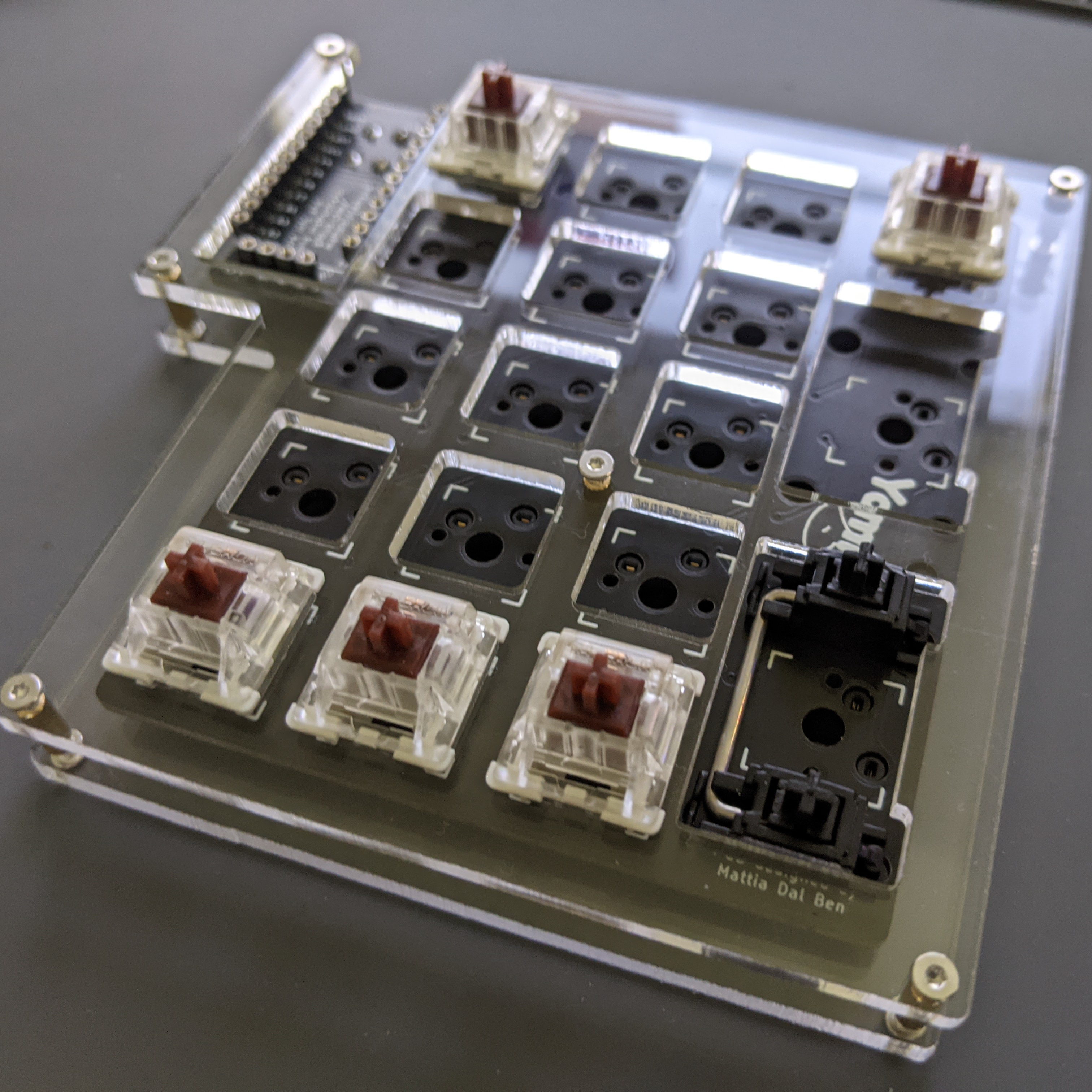
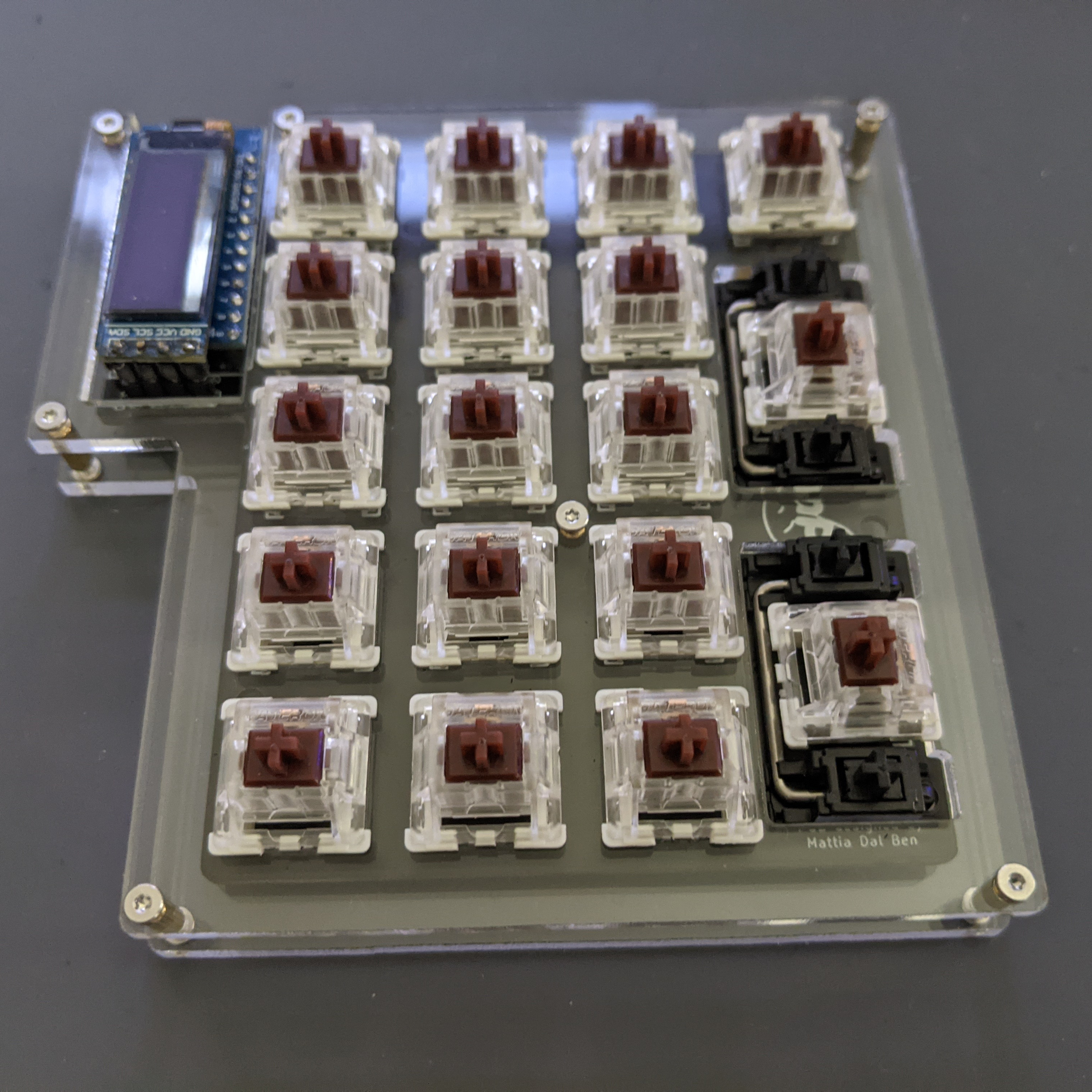
4. Install Switches
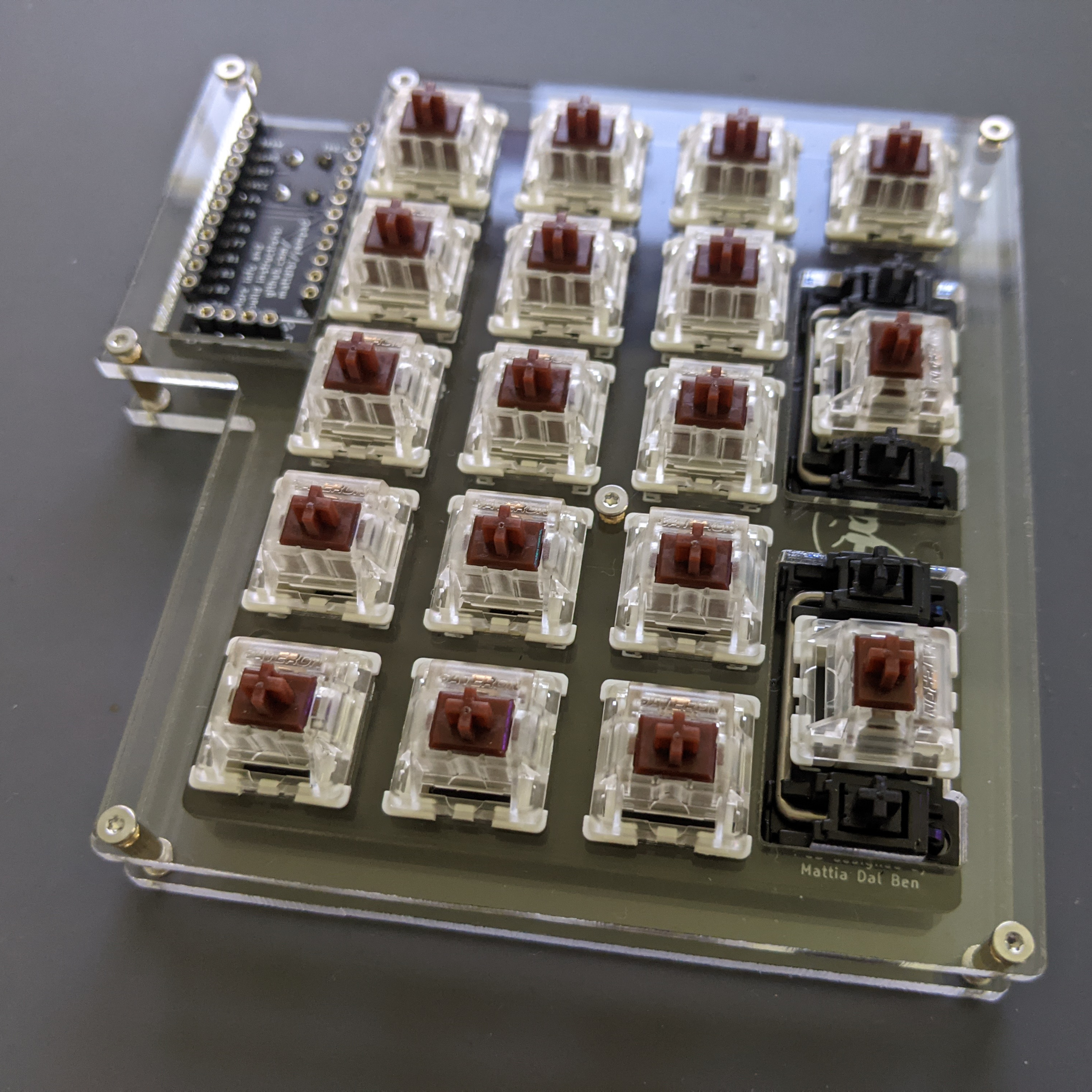
Your switches can now be press fit into the Kailh sockets.
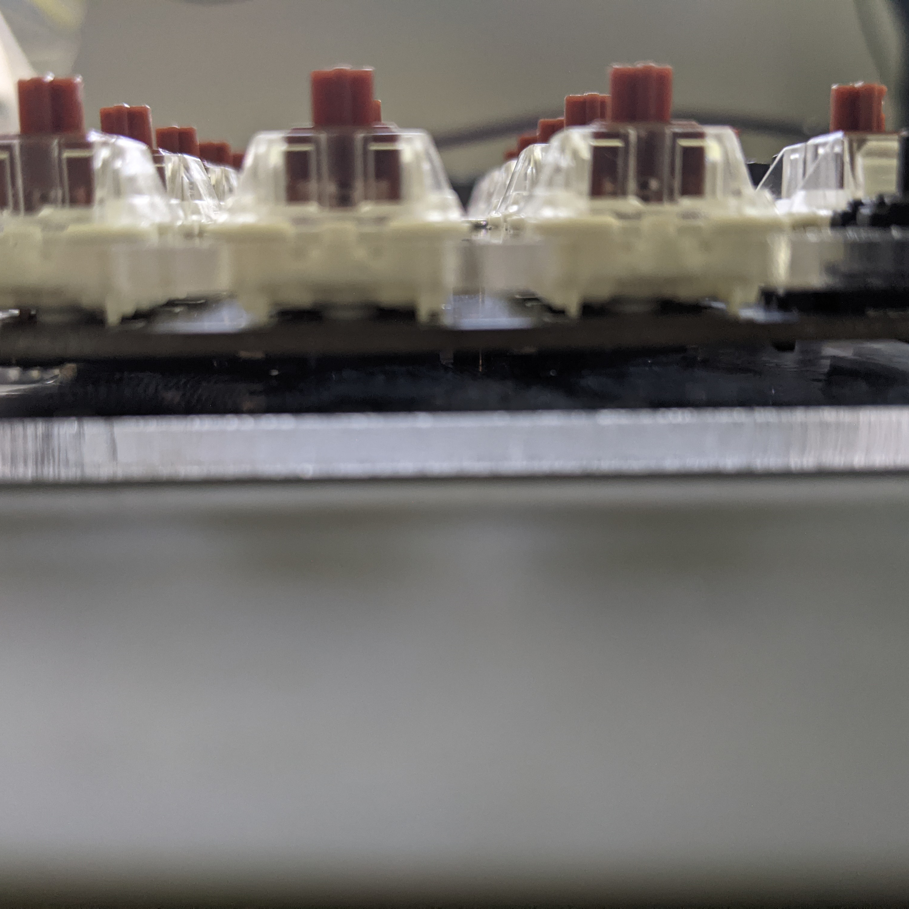
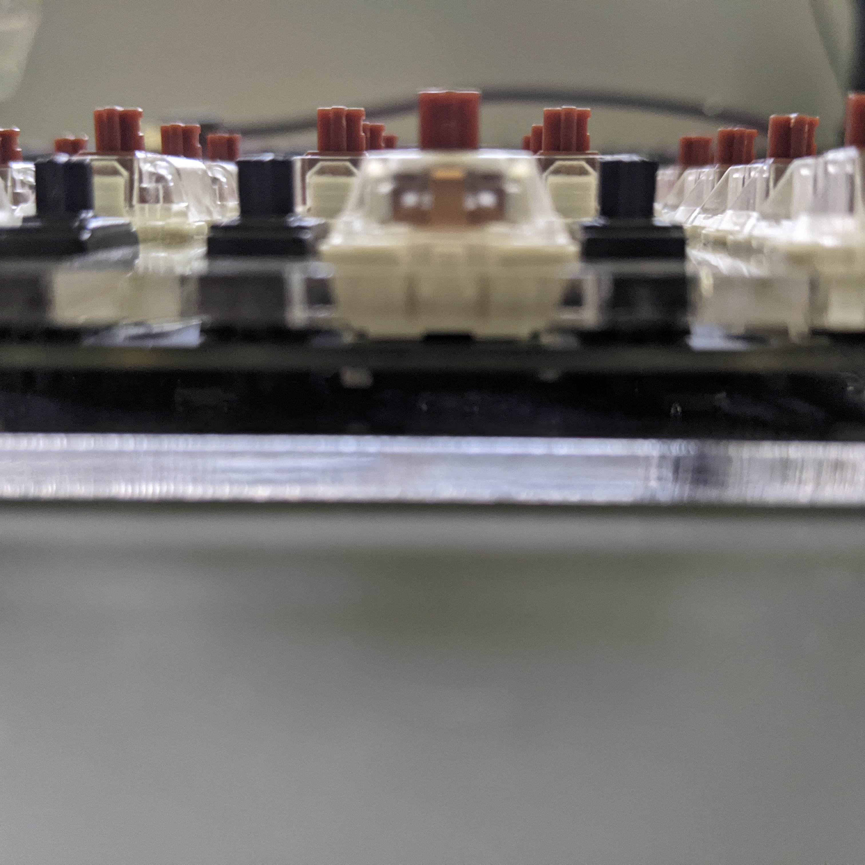
Looking from the side to make sure the switches are pushed firmly onto the PCB and there are limited gaps.
5. Connect OLED Display
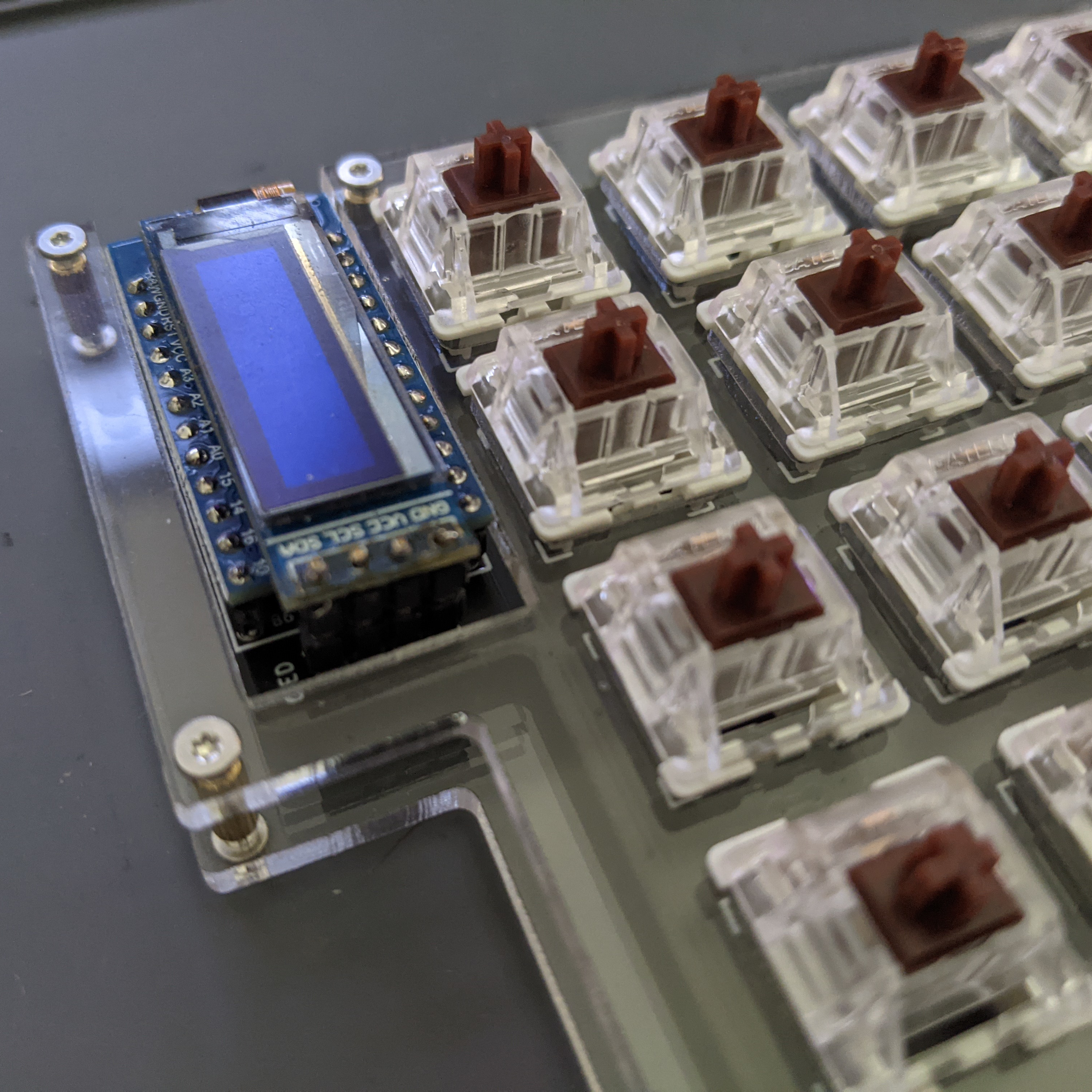
If you direct attached your OLD display above then you can skip this step otherwise you can now install the display using diode-legs or thin wire as legs into the machined header pins. This allows for the display to be removed, replace, upgraded as well as easy access to the controller.
6. Stick on Feet
Place one rubber foot onto each corner of the Yampad case.
All done!