Fourier v1.3 Build Guide
Parts List
Here’s a list of parts needed for the build:
-
Kit Includes:
- 2 x Fourier PCBs (Left/Right)
- 2 x Fourier Switch Plates (Left/Right)
- 2 x Reset Buttons
- 2 x 4.7kΩ Resistors
- 2 x TRRS Jacks
- 1 x TRS Cable
- 49 x 1N4148 Diodes - through hole (included in kit) and SMD diodes supported
- 10 x M2 6mm Hex Screws
- 10 x M2 4mm Hex Screws
- 10 x M2 10mm Standoffs
- 8 x Clear Rubber Feet
Not included in the kit but required to complete:
- 2 x Pro Micro Controllers
- 1 x Micro USB Cable
- PCB-mount MX stabilizers
- MX or Alps compatible keyswitches
- WS2812B Compatible RGB LED strip (optional, for underglow)
Build Steps
- Prepare components
- Solder components
- Solder Diodes
- Solder 4.7kΩ Resistors (optional)
- Solder TRRS Jacks
- Solder Reset Button
- Solder Pro Micro Header Pins
- Solder Switches
- Solder Pro Micro
- Solder RGB strip (optional)
- Acrylic Case
1. Prepare Components
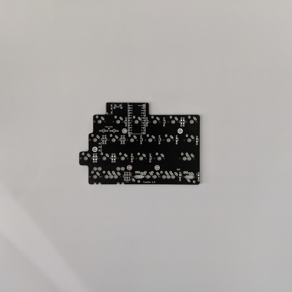
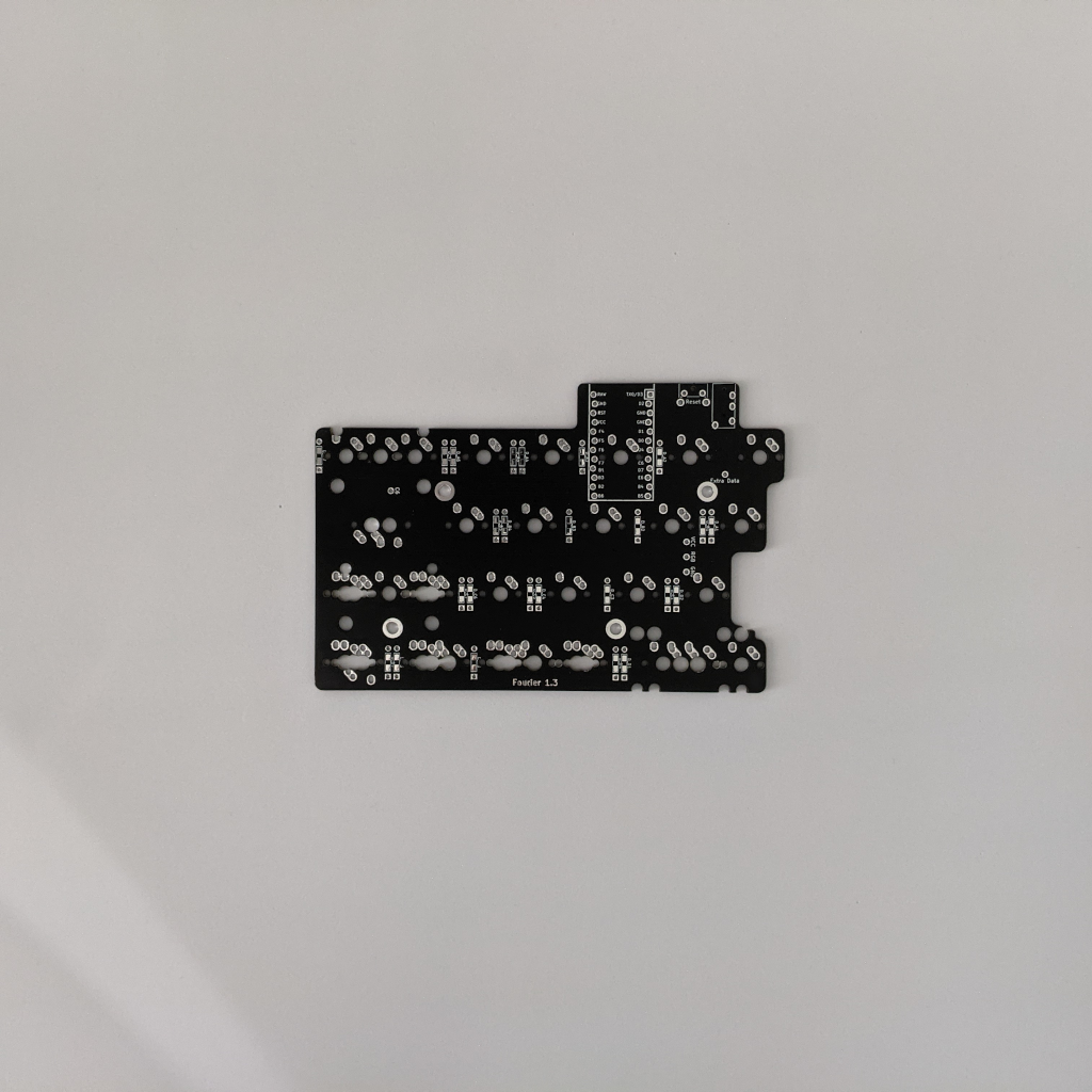
Grab your PCBs. Pictured bottoms up. Left is on the left, right is on the right.
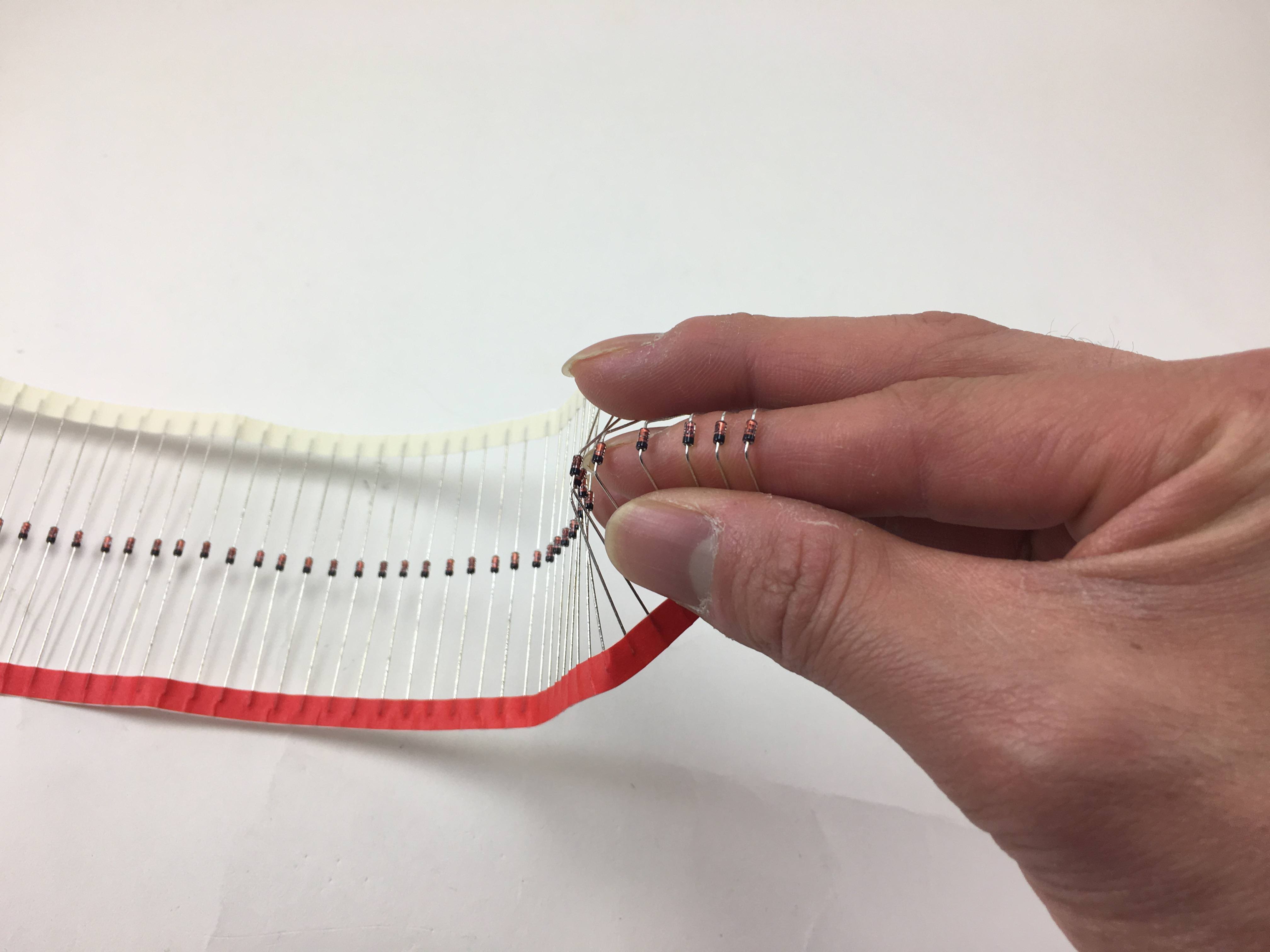
If you’re using through hole diodes, bend them into shape. Here, I’m just bending it around my finger
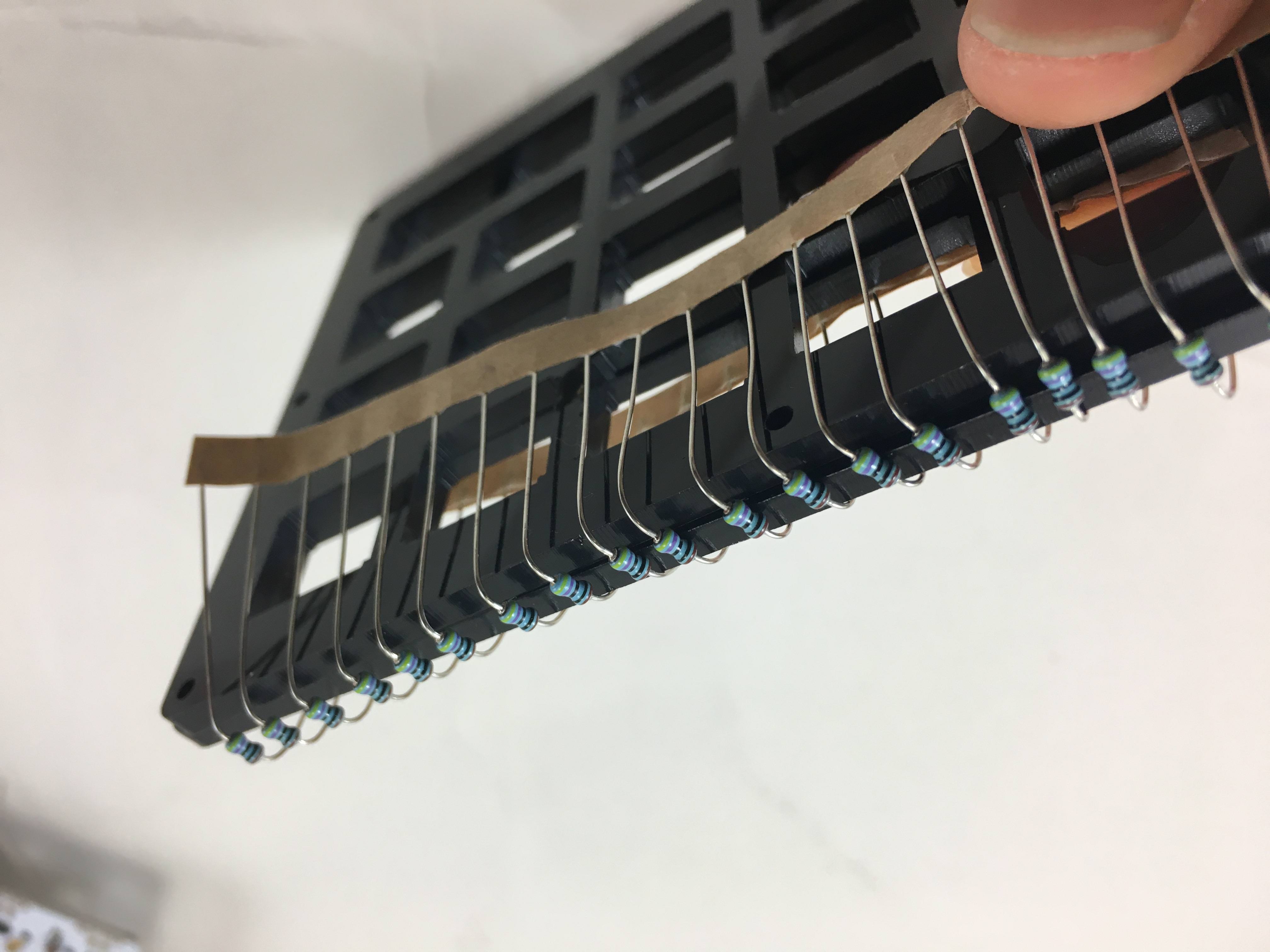
Another way to do it, resistors shown here
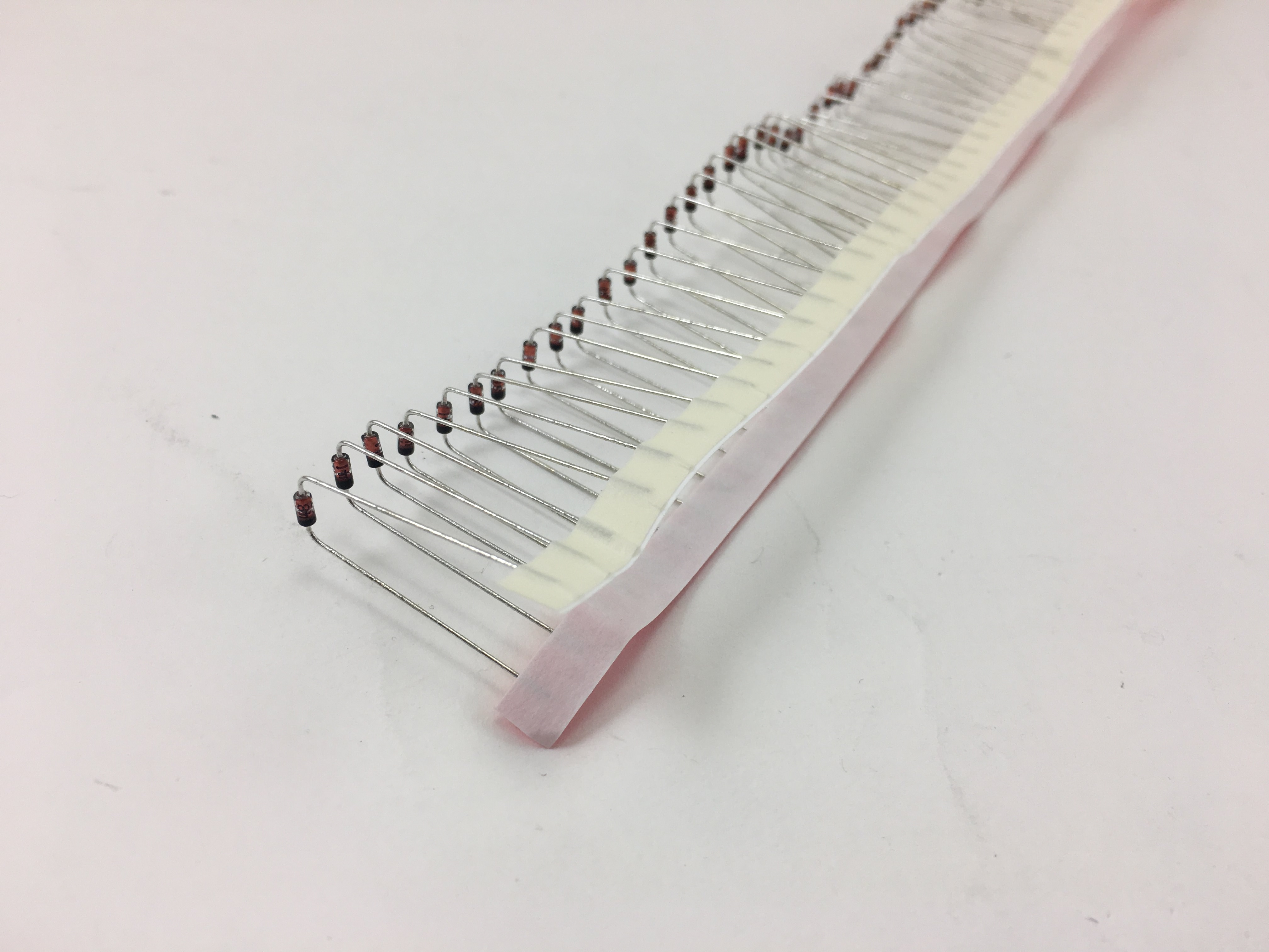
Strip of diodes bent
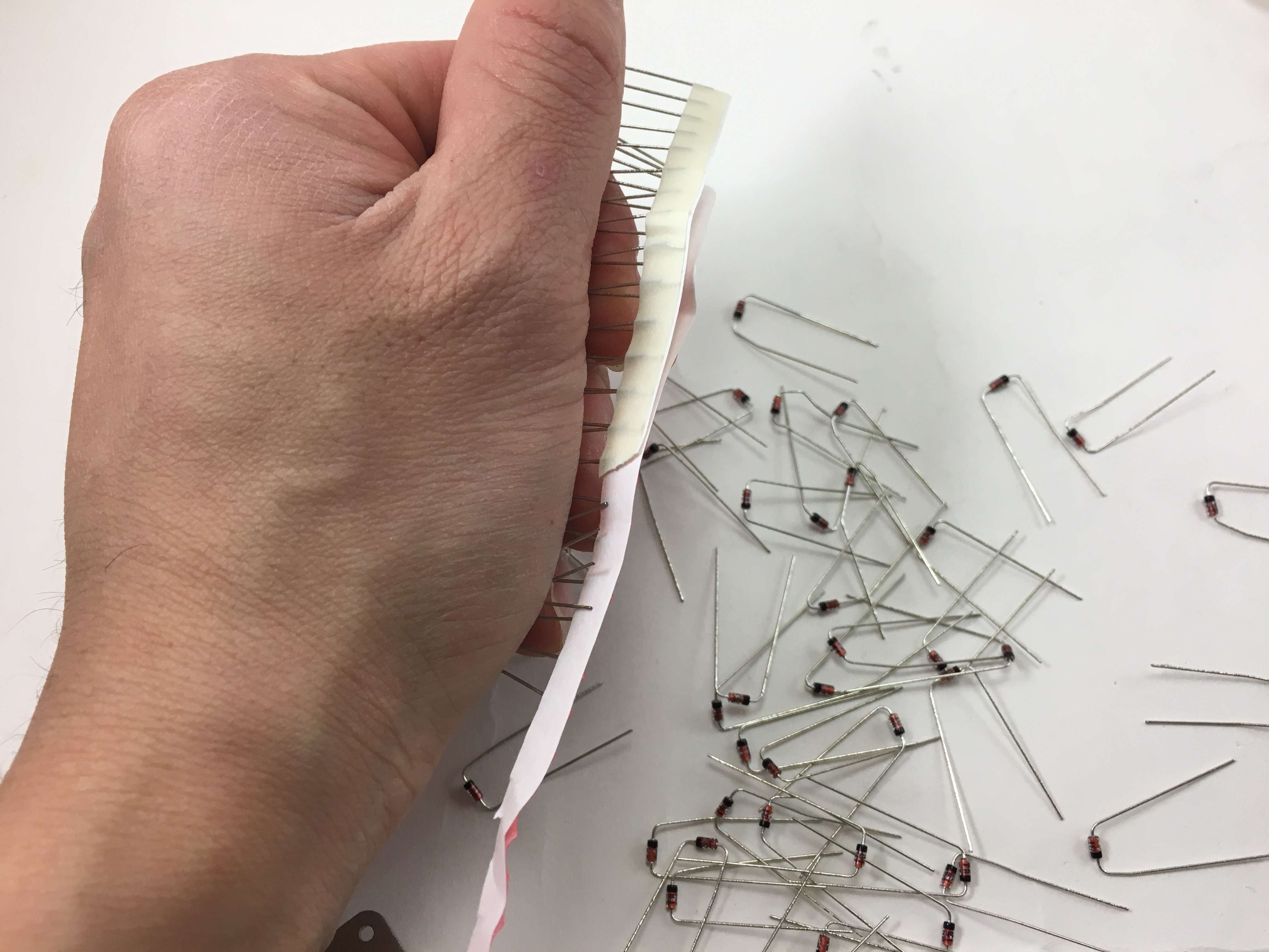
Ripping off the paper holding all the resistors together. Grip the diodes tightly so they don’t bend as you’re ripping the paper off.
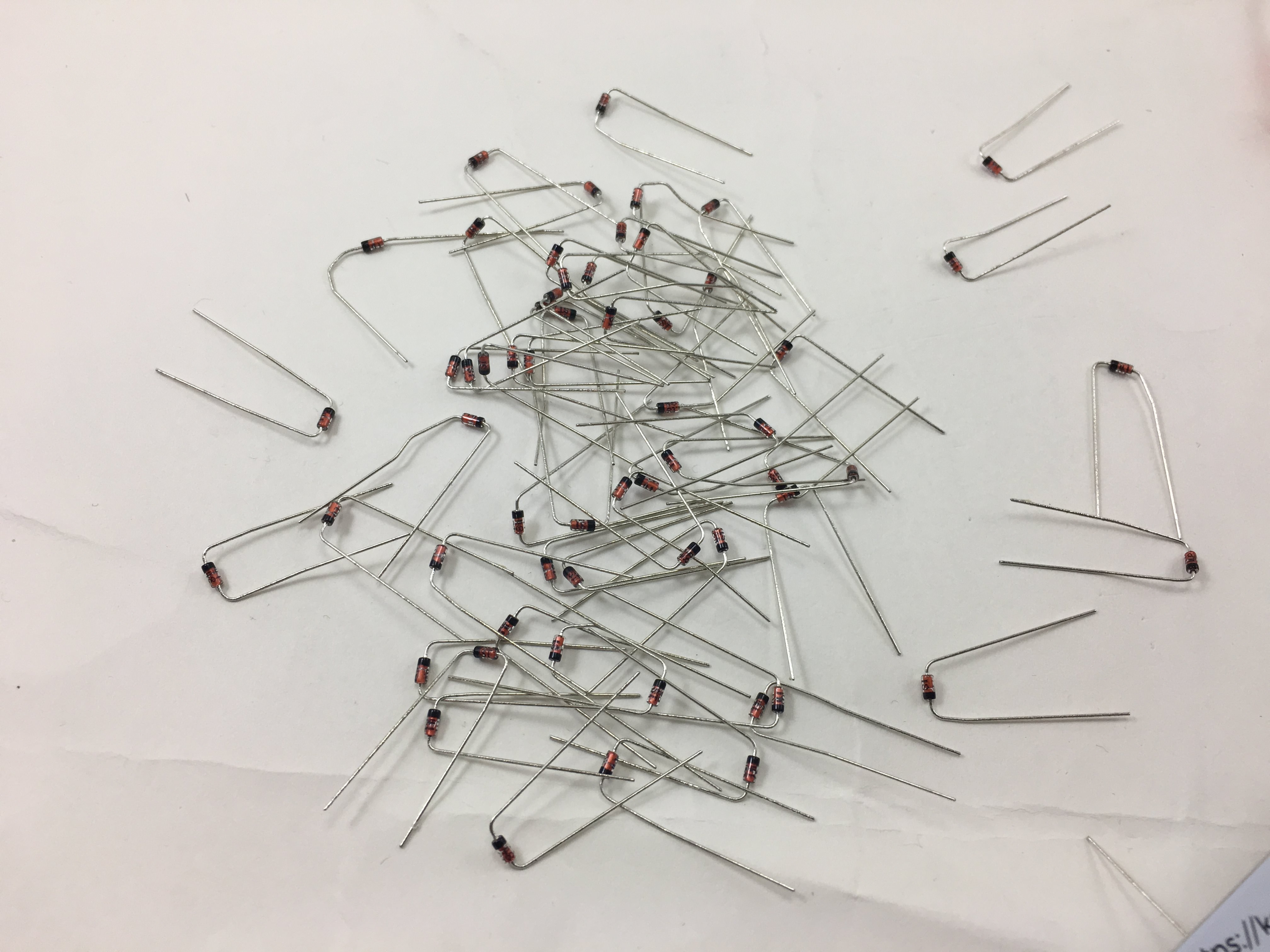
All separated from the paper
2. Solder Components
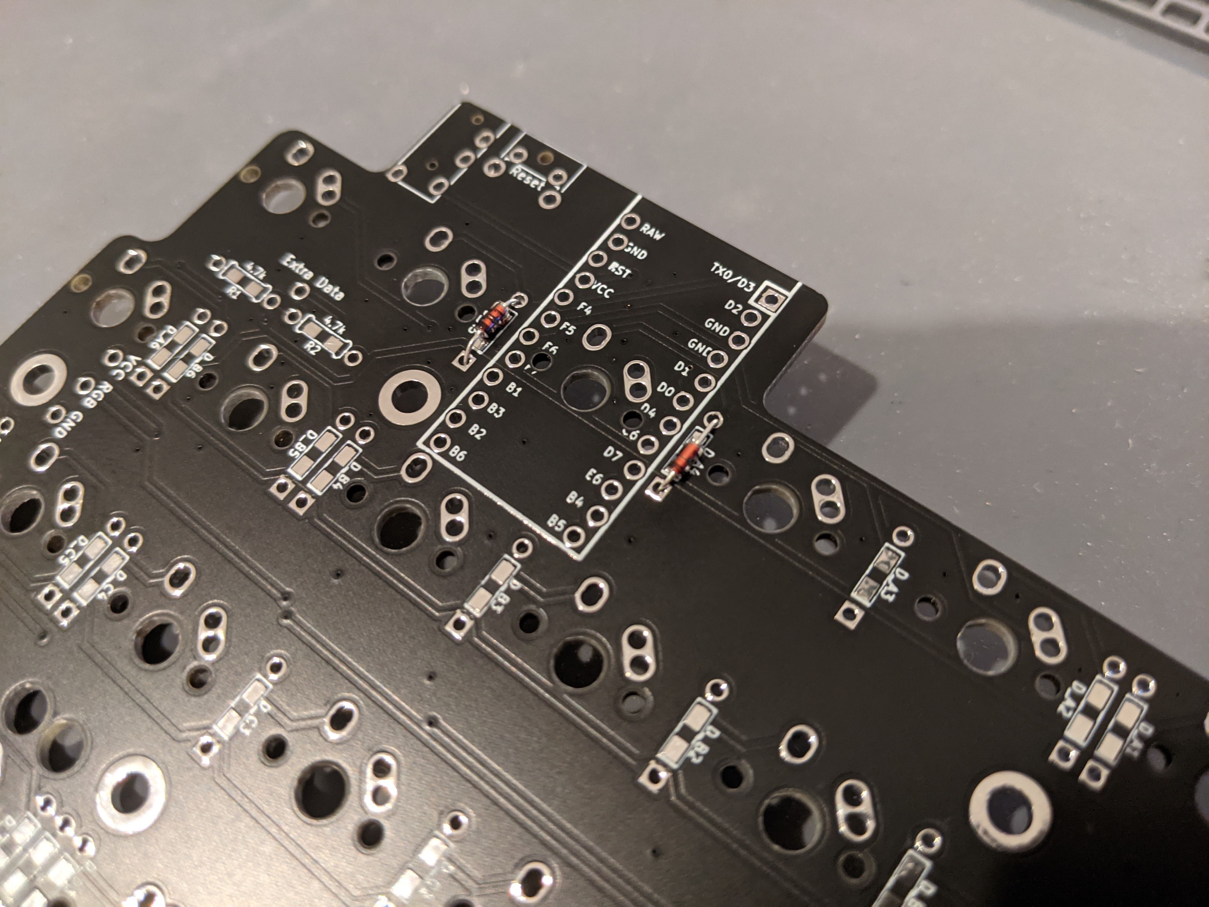
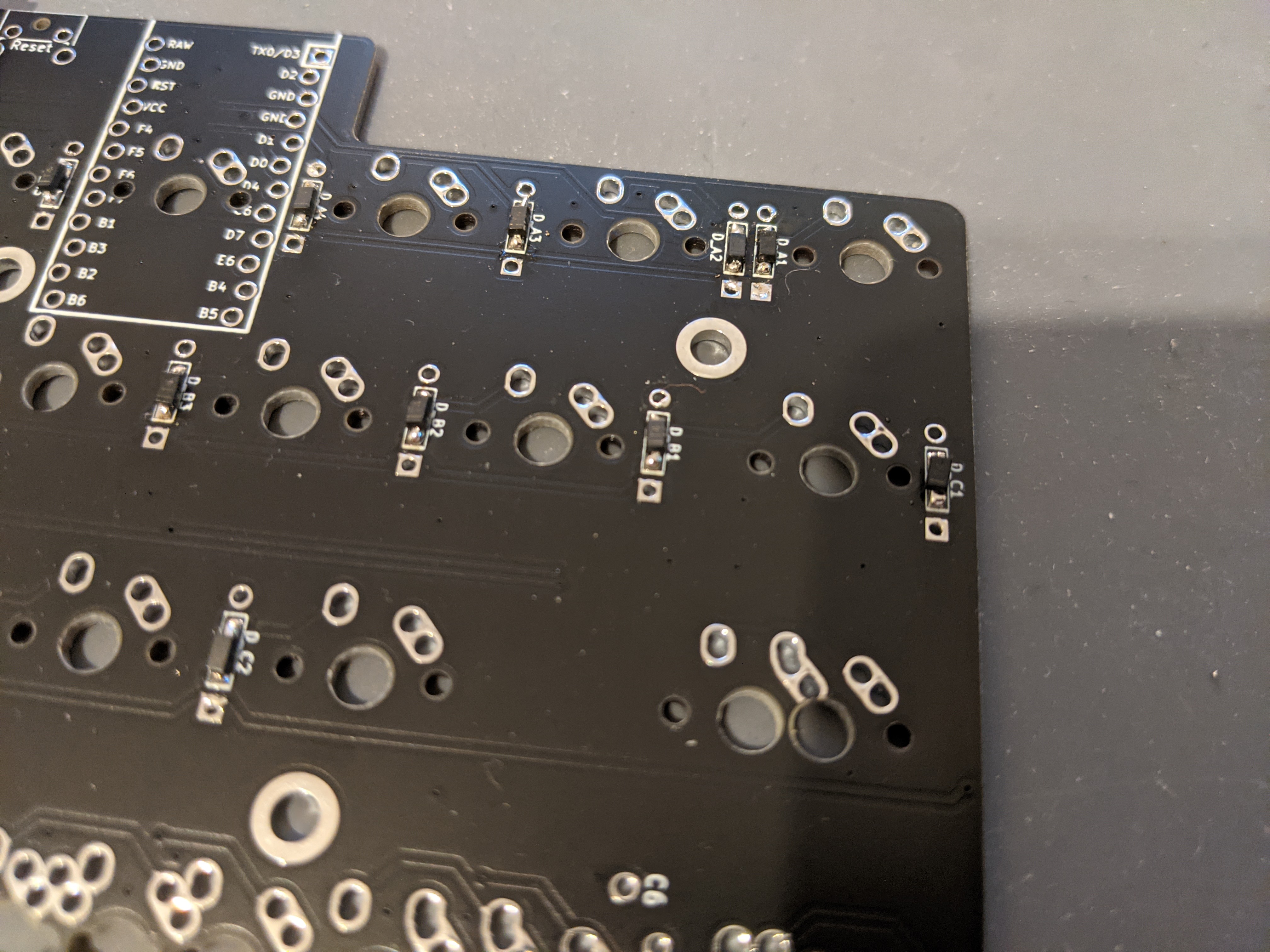
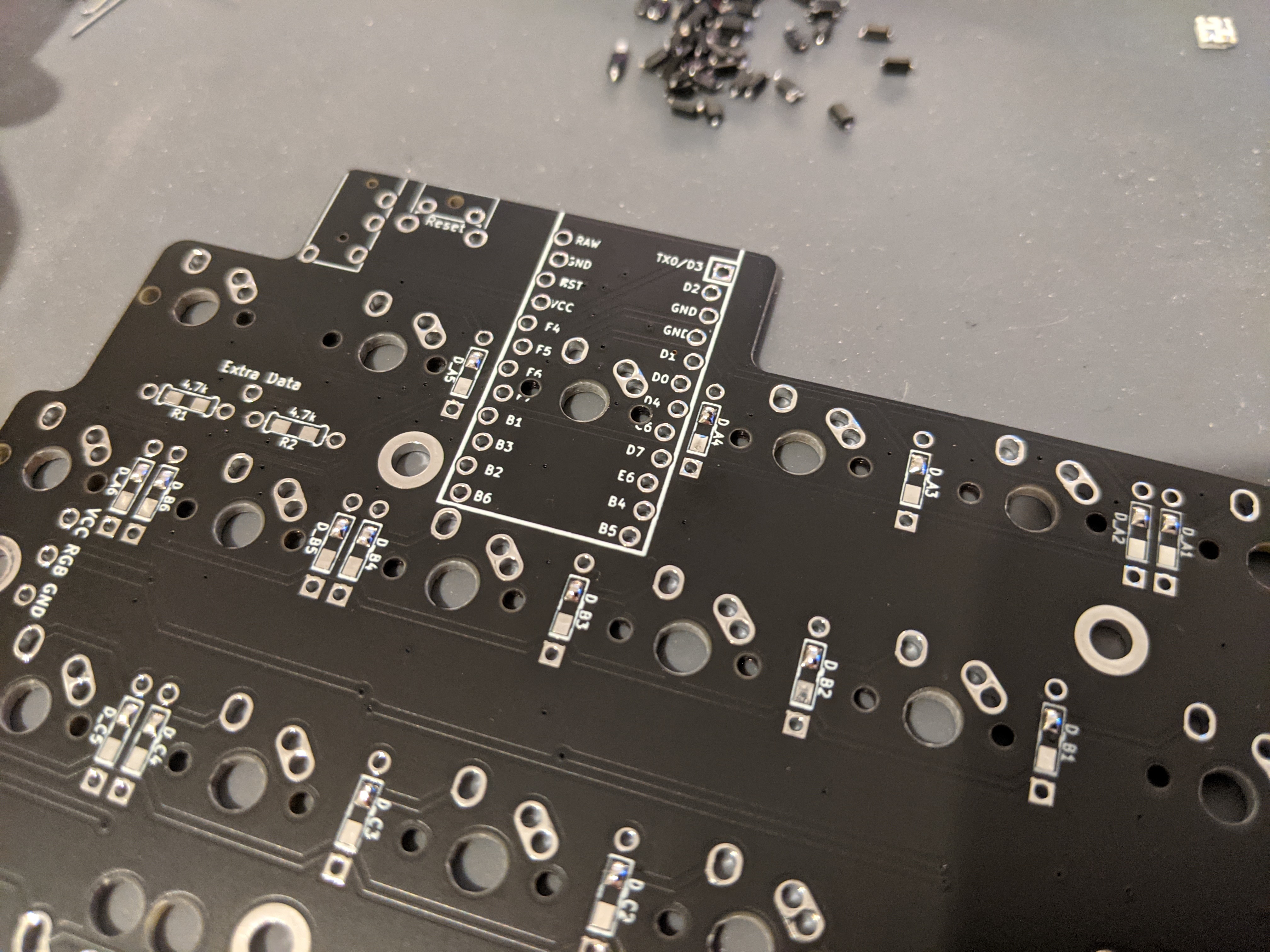
Install either the through hole or SMD diodes (example shown above). SMD diodes will be used for the following steps.
The orientation of all the diodes are the same, they are vertically oriented, with the band/line on the diodes facing towards the bottom, square pad.
SMD diodes have a white band and through-hole diodes will have a black band.
Add a small amount of solder to one of the diode pads first.

Hold the diode with tweezers and melt the solder on the pad before placing the diode into position. Let the solder cool to hold the diode in place. Add some solder to the other side of the diode to ensure a good connection on both ends.
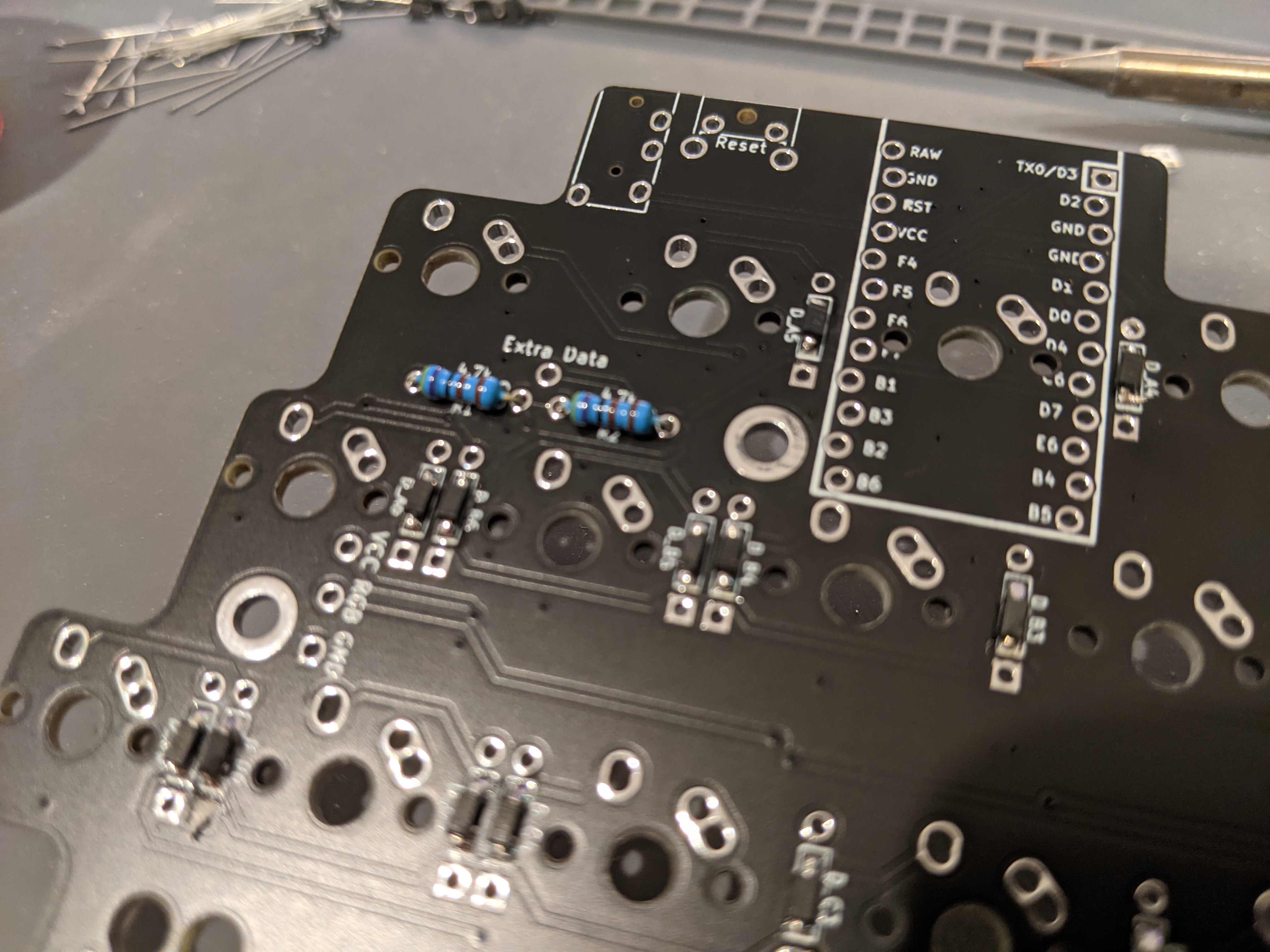
Install the I2C resistors (optional).
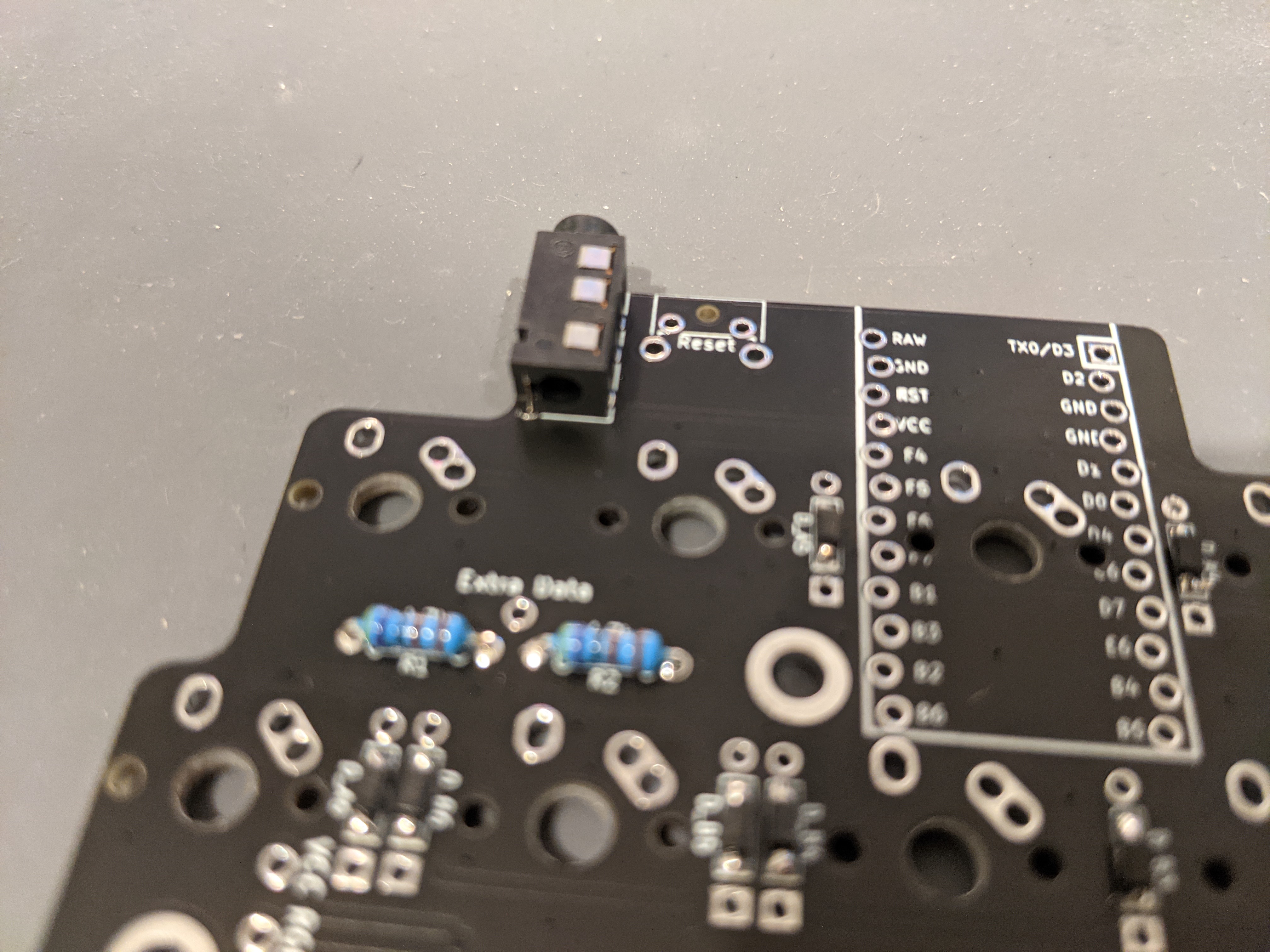
Install the TRRS jack.
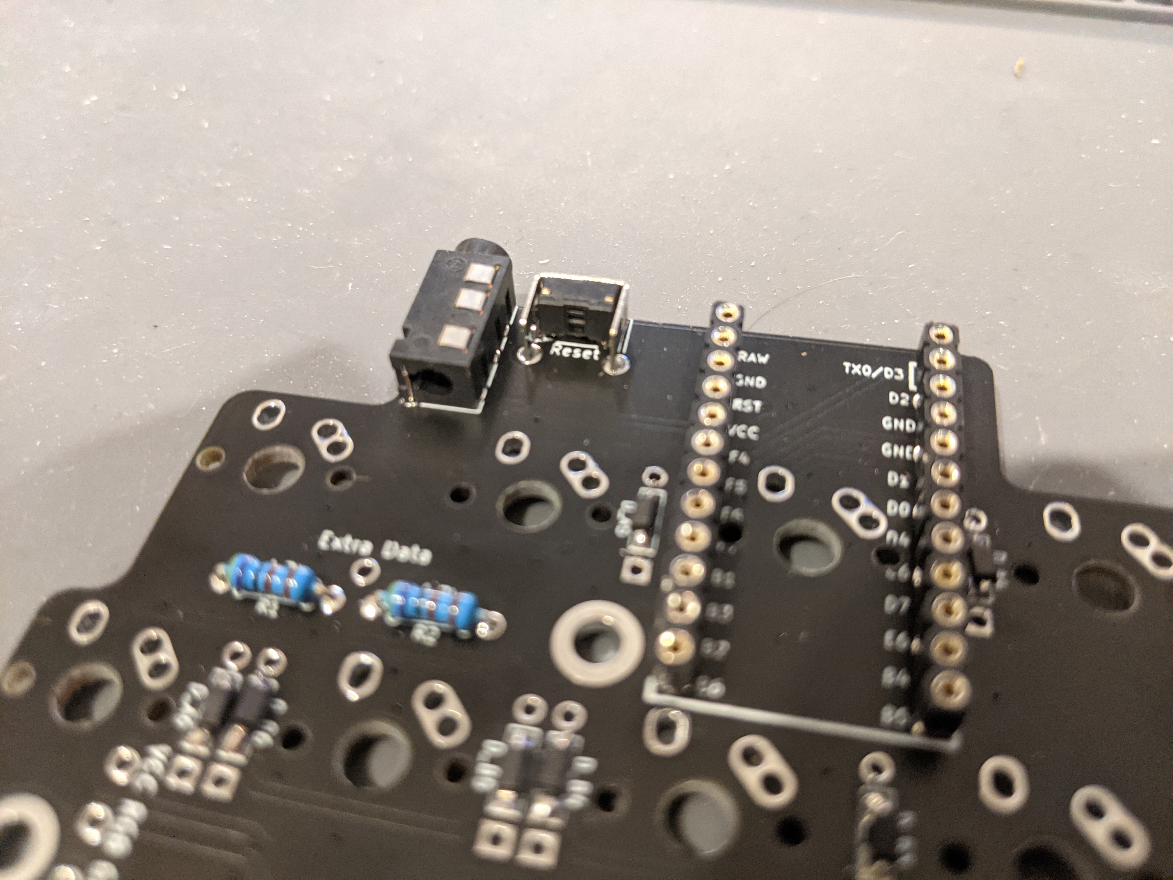
Install the reset switch and controller header pins.
NOTE: DO NOT direct attach the controller until you solder the switches. You can add the controller here only if you are socketing it as there is a switch that needs to be soldered underneath the controller on both halves.
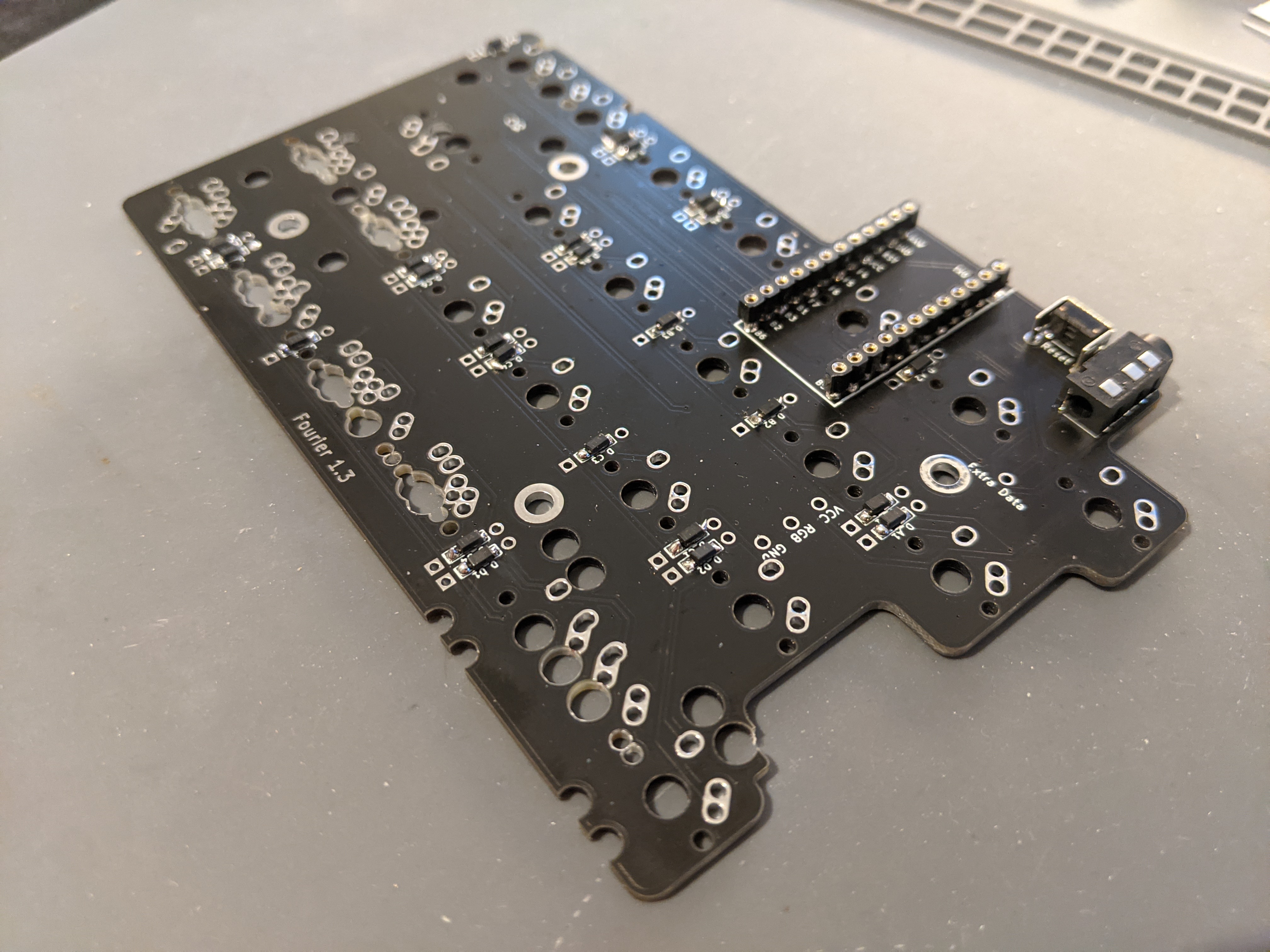
Repeat the same process with the diodes, TRRS jack, reset switch and controller header pins with the right half. Note that there’s no I2C resistor slots on this side, as they’re only needed on one half.
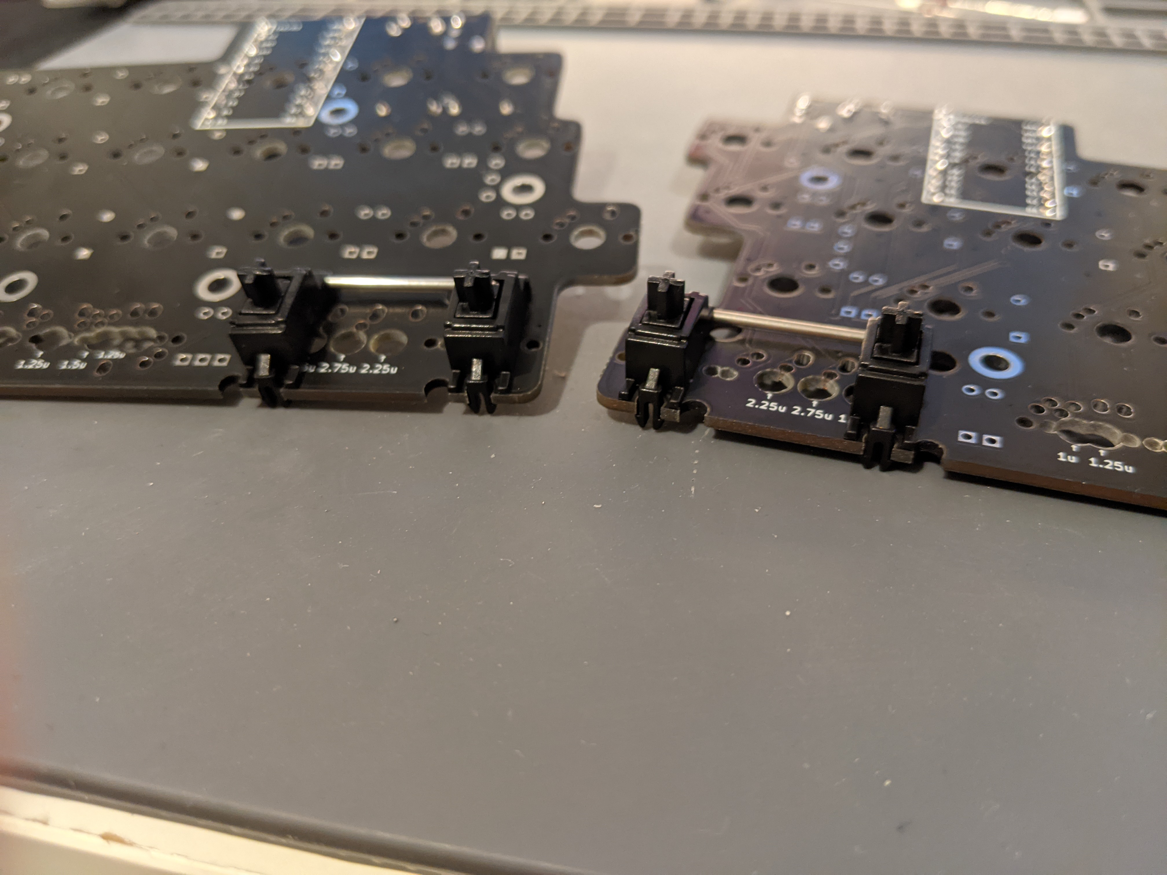
Add stabilizers to the keys you want to stabilize.
3. Solder Switches
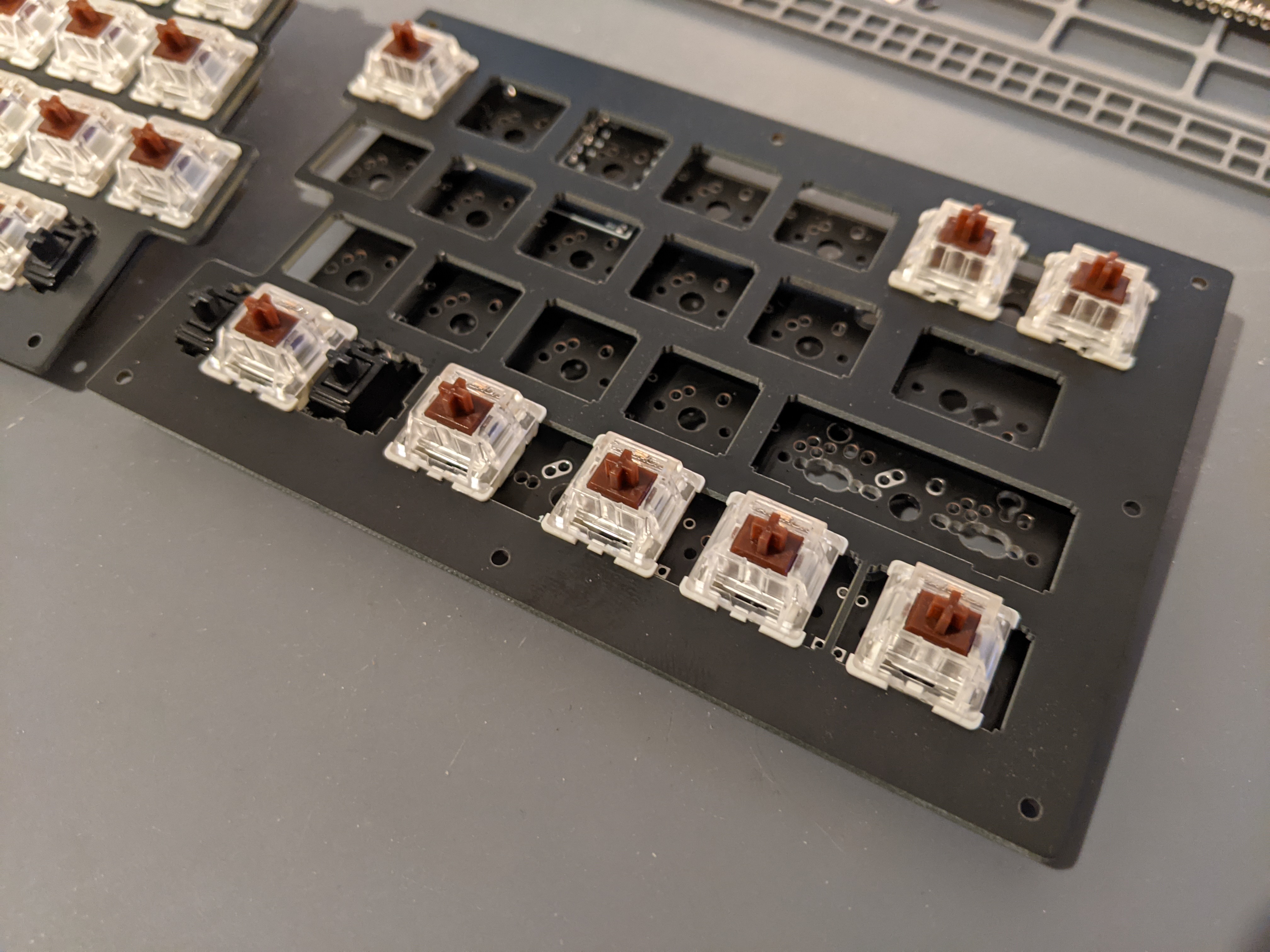
Time to add the switches. Put a few switches into the corners of the switch plate and then attach the switches to the PCB. Make sure the switches are pushed all the way down onto the PCB.
Due to the multiple layout options, it may be helpful to put keycaps on the switches to make sure everything is in the correct slots.
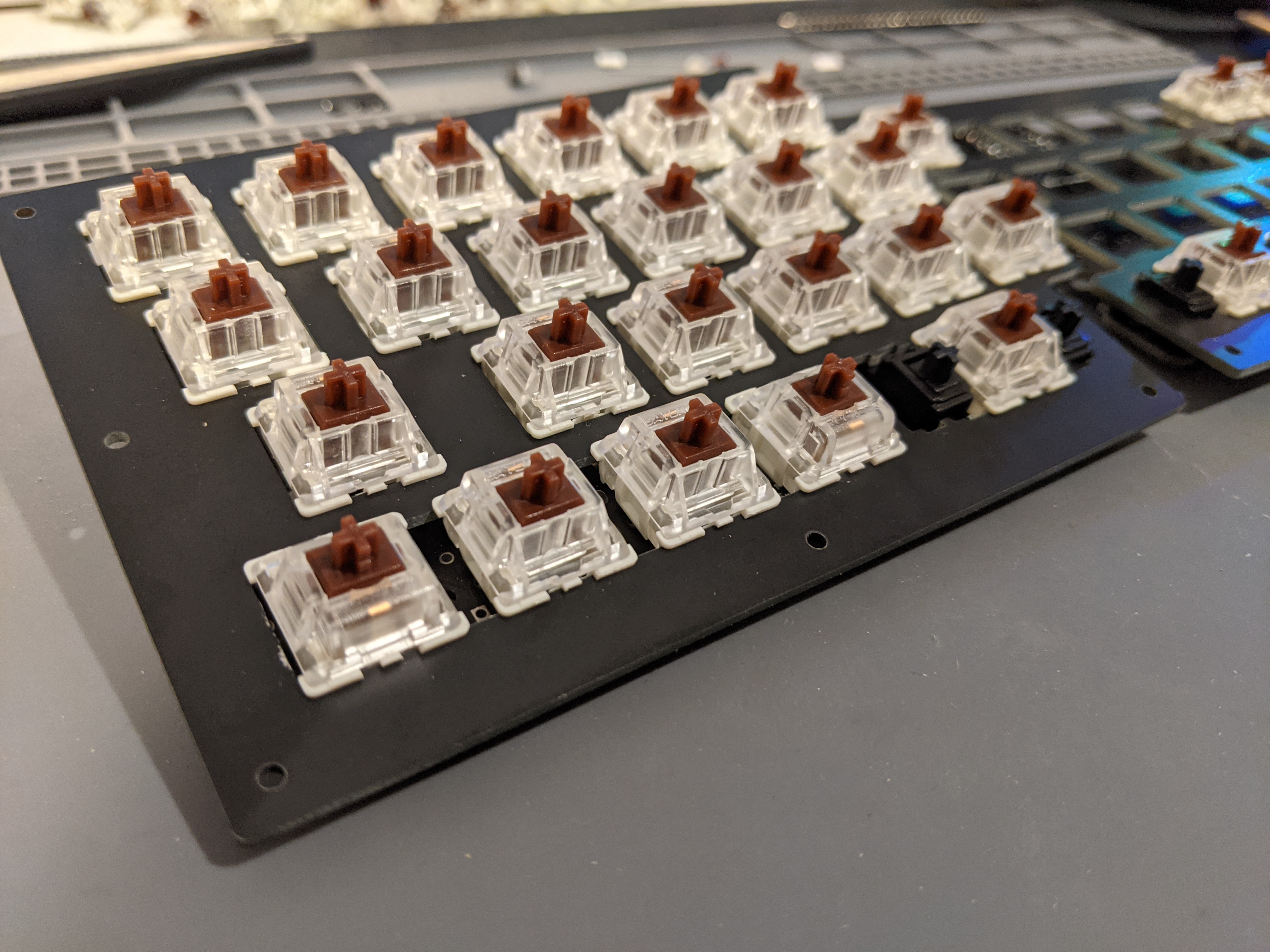
All the switches installed and soldered in.
4. Solder Pro Micro
Time to install the Pro Micro now that the switches have been soldered in.
Flash your Pro Micro before installing it on the board to ensure it works as expected and the controller connects to the PCB face down (so you cannot see the controller components)
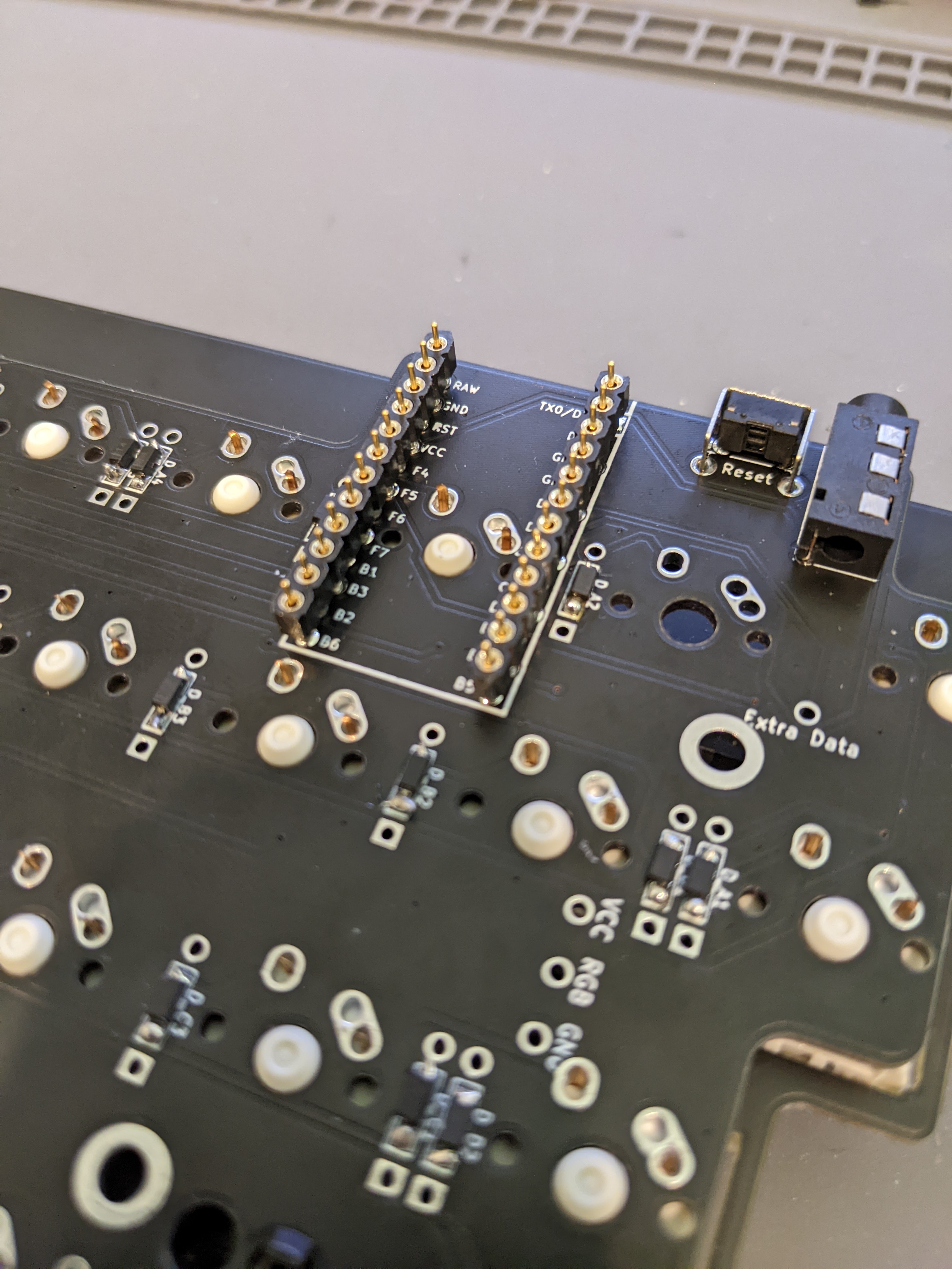
If using Mill-Max pins to socket the Controller place them into the machined headers.
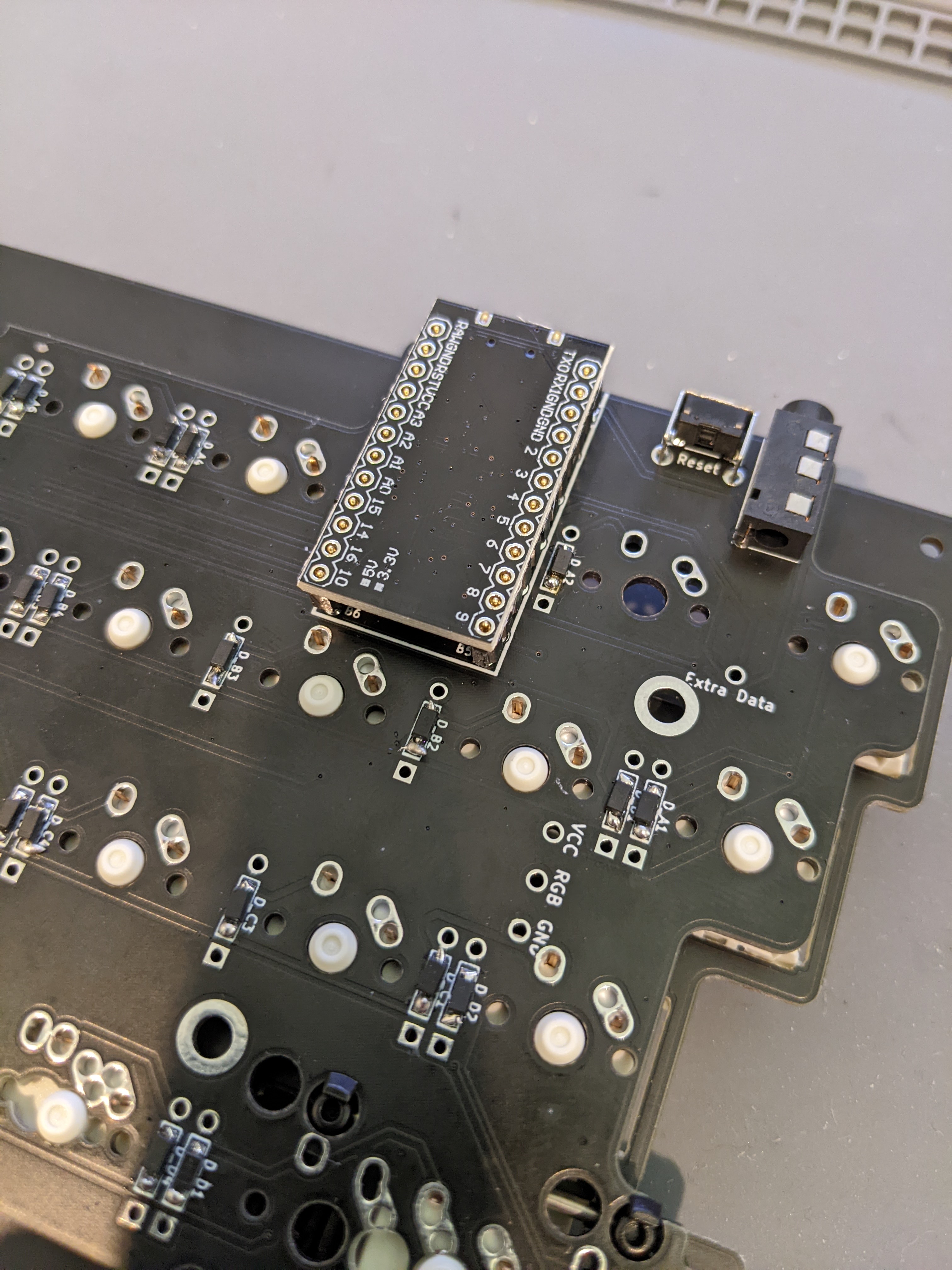
Place Controller onto the Mill-Max pins and solder into place.
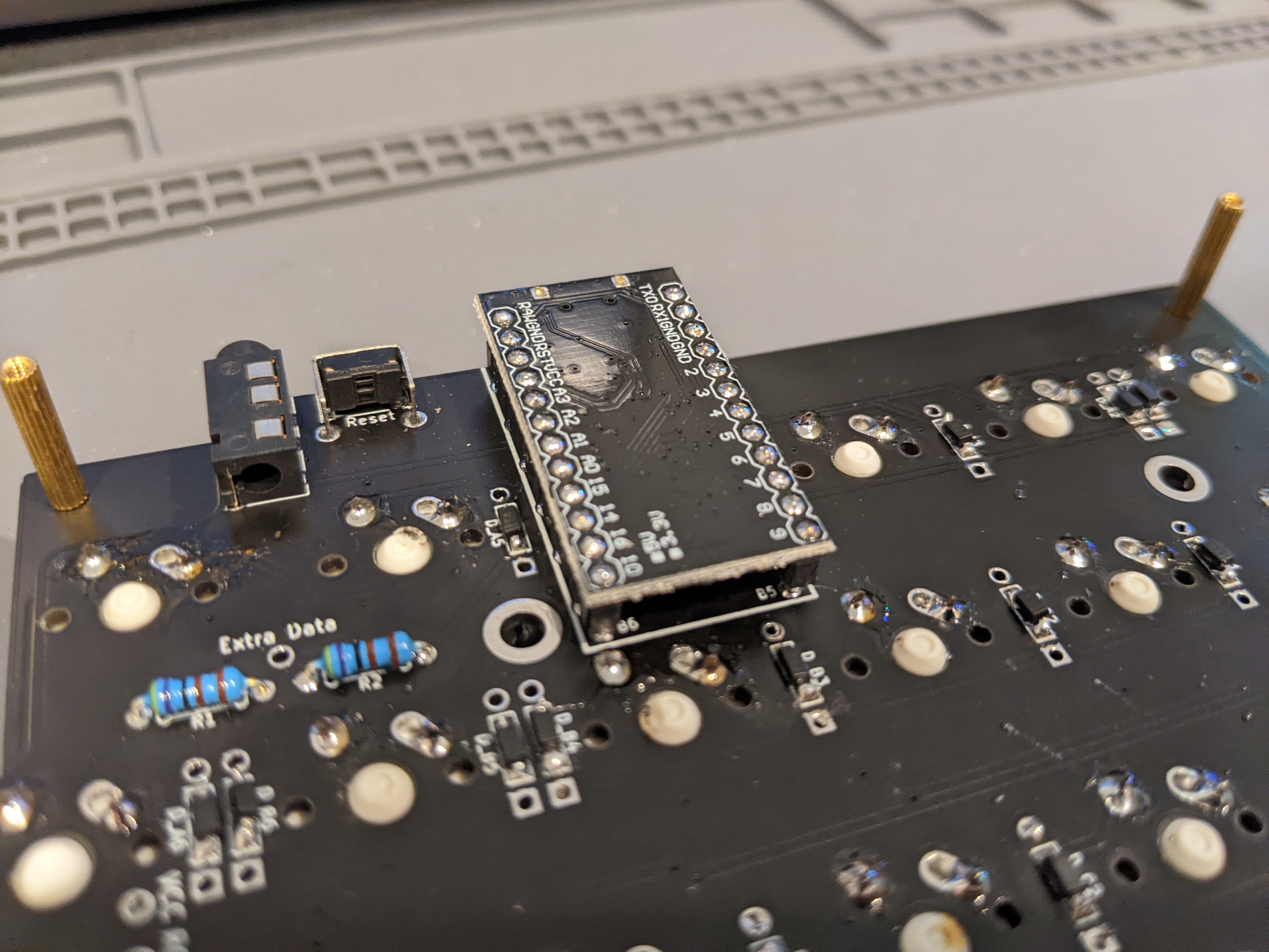
Soldering complete for each of the pins into the Controller.
Repeat the process of stabilizer, switch, and Pro Micro installation on the right PCB.
Once again, the component side of the Pro Micro will be hidden from you.
5. Solder RGB Strip (Optional)

Optional, add the RGB strip to the backside of the PCB and solder to the following points:
Left Side
- RGB breakout goes to Din on strip
- VCC breakout goes to +5V on strip
- GND breakout goes to GND on strip
- Extra Data goes to Do/Dout on strip

Right Side
- VCC breakout goes to +5V on strip
- GND breakout goes to GND on strip
- Extra Data goes to Din on strip
- RGB breakout remains empty for now
6. Acrylic Case
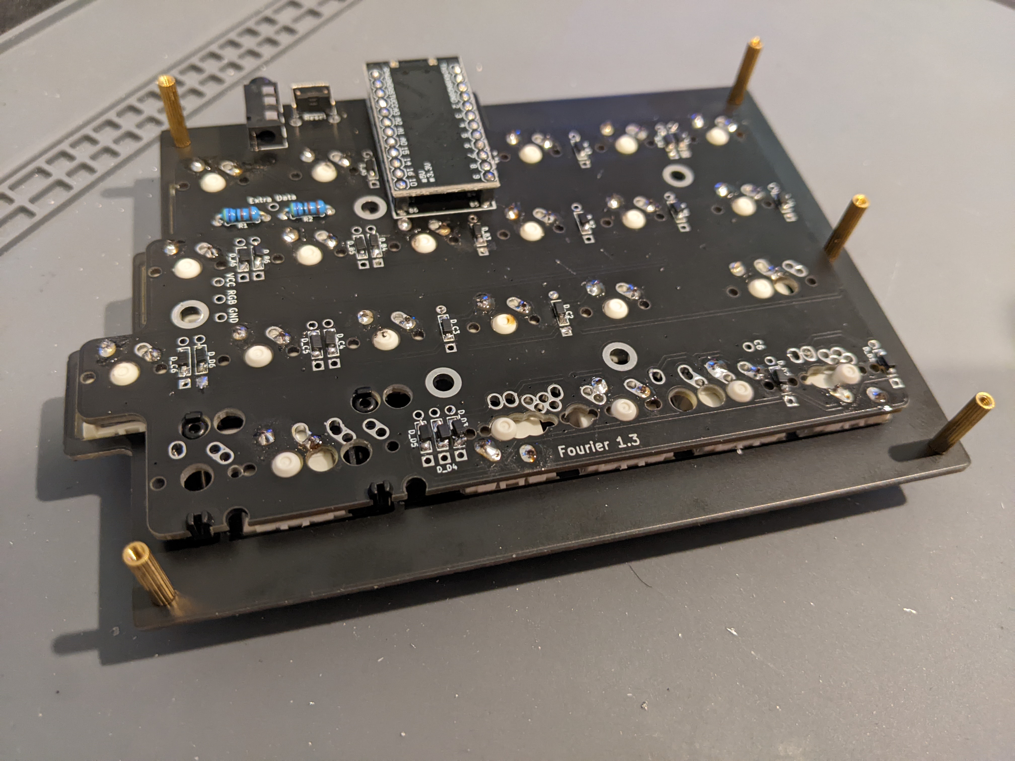
Using 5 of the 4mm Hex Screws, attach the Standoffs as shown above.
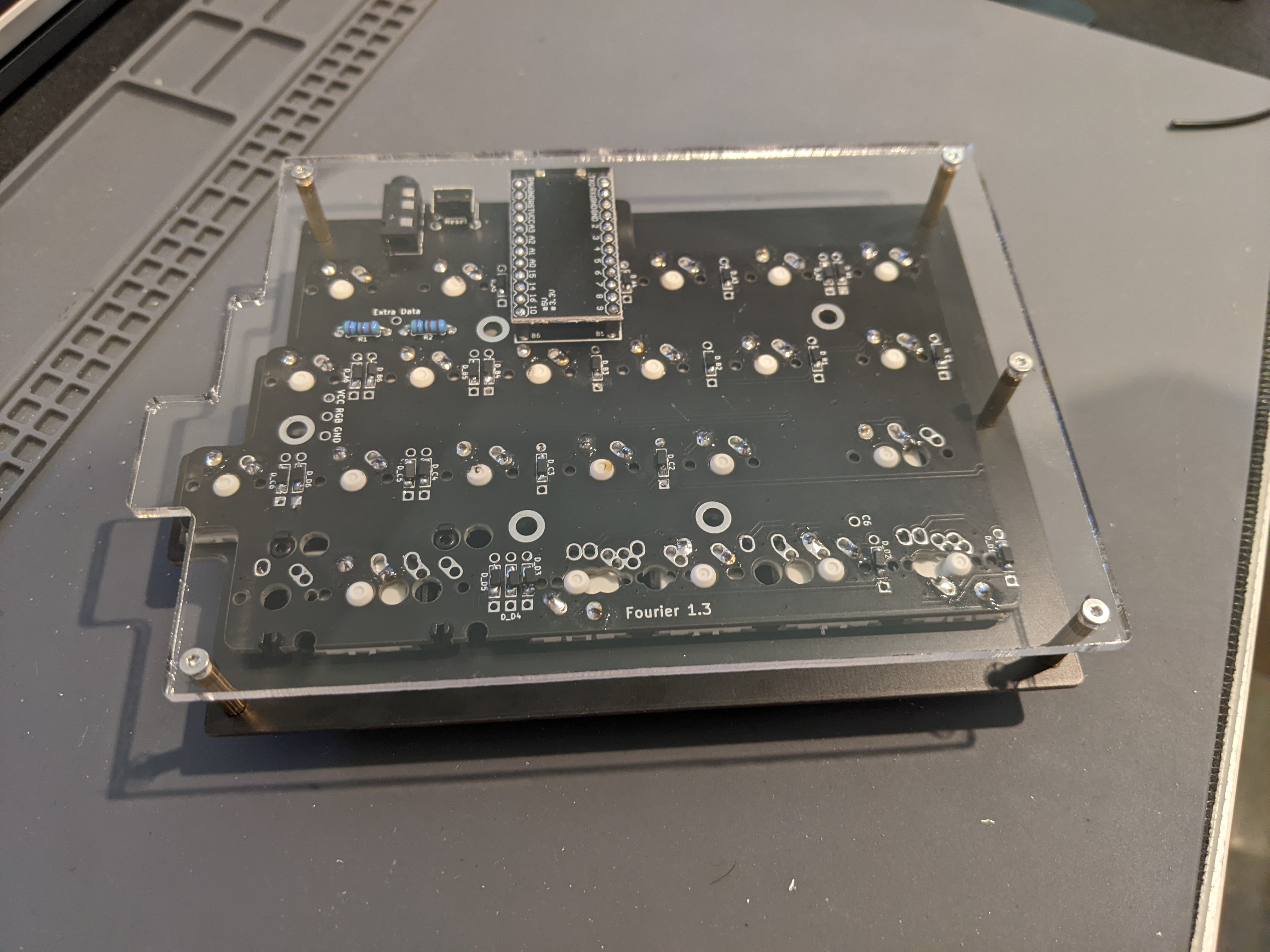
Peel the protective layer from the Acrylic base plates and using 5 of the 6mm Hex Screws, attach the Acrylic bottom plates to Standoffs.
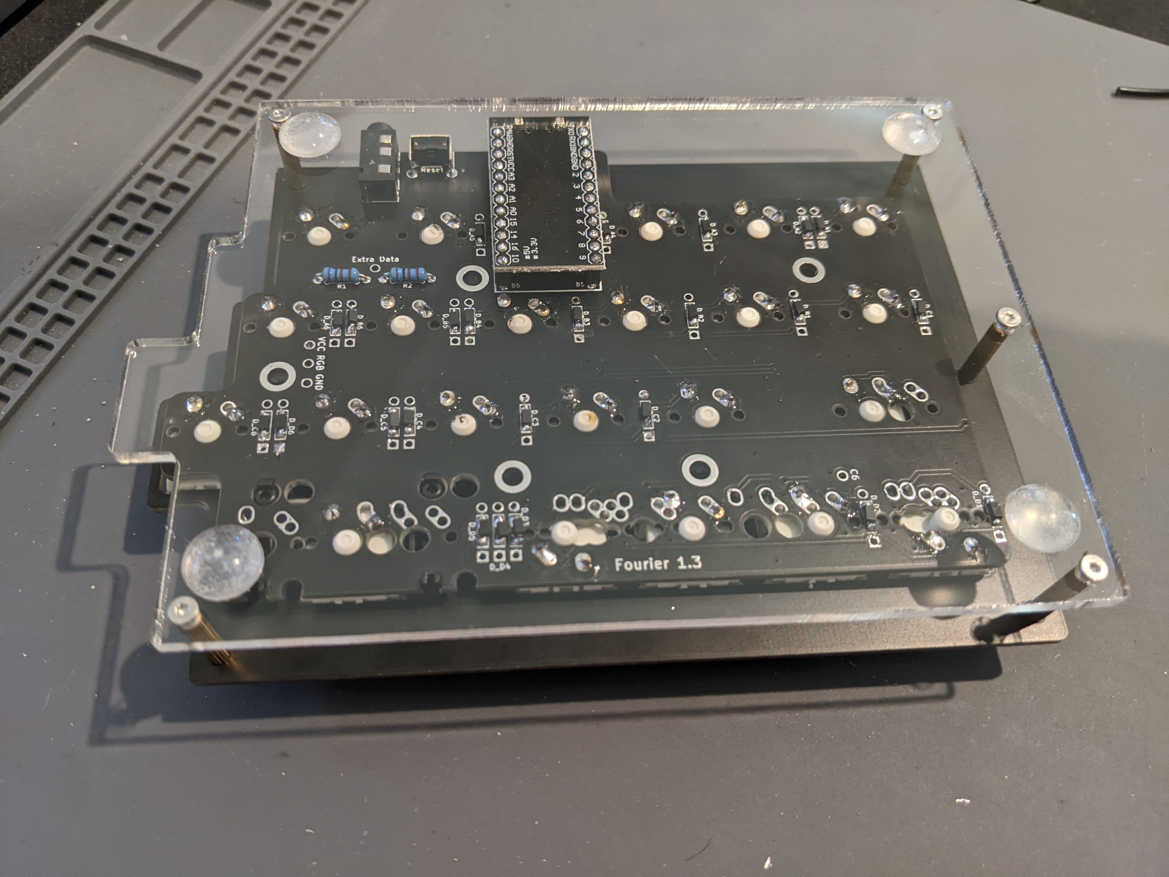
Using 4 rubber feet, add one to each corner.
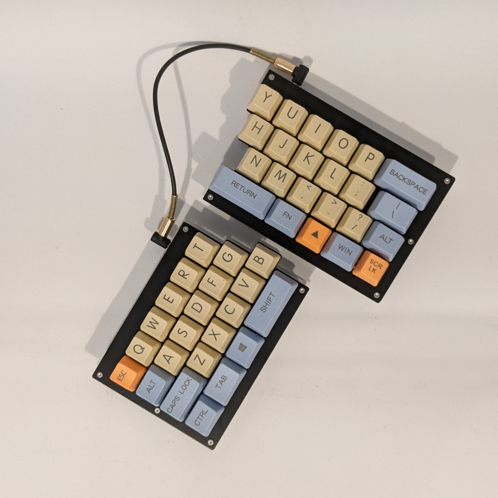
Repeat the above 3 steps on the right side and you are done!
Complete with screws, standoffs, and bottom plates.