Build Steps
The Reviung 39 Mk-II is a surface-mount, hotswap build: the diodes, LEDs and switch sockets are all soldered to the PCB, and your switches simply push into the sockets afterwards. We'll prepare the controller first, then solder the SMD components from smallest to largest before assembling the plate stack.
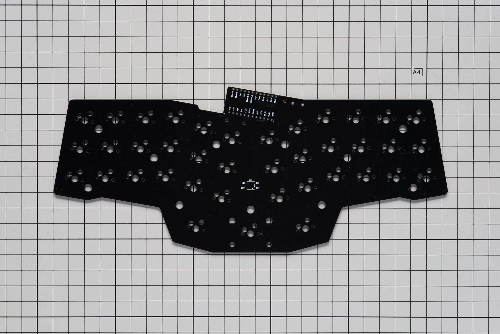
The front of the main PCB (switches and top plate mount here):
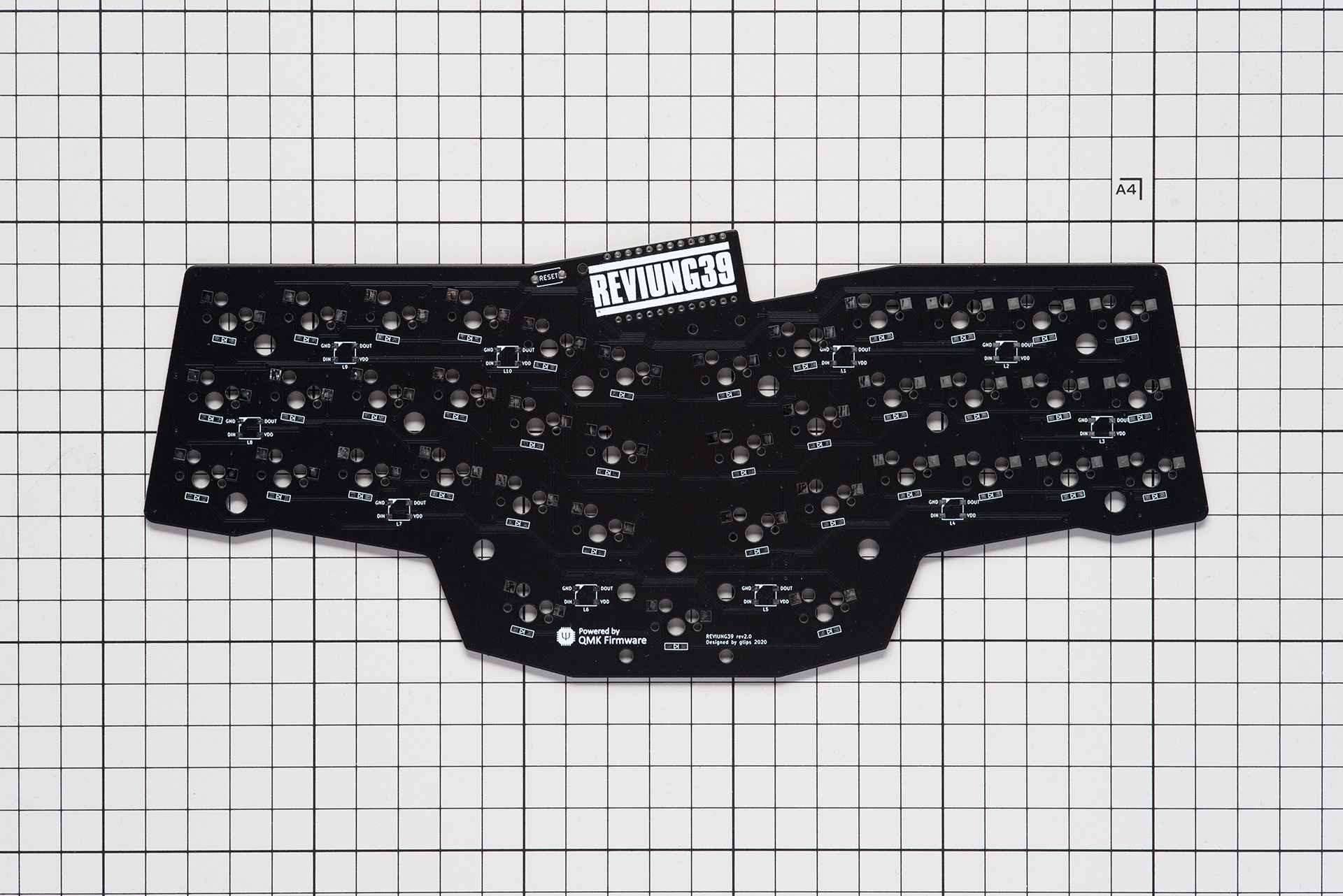
The back of the main PCB (reset switch and hotswap sockets mount here):
Have no-clean flux and fine tweezers on hand before you start. Surface-mount work is far easier with flux, and every SMD part is placed with tweezers.
1. Prepare the Controller
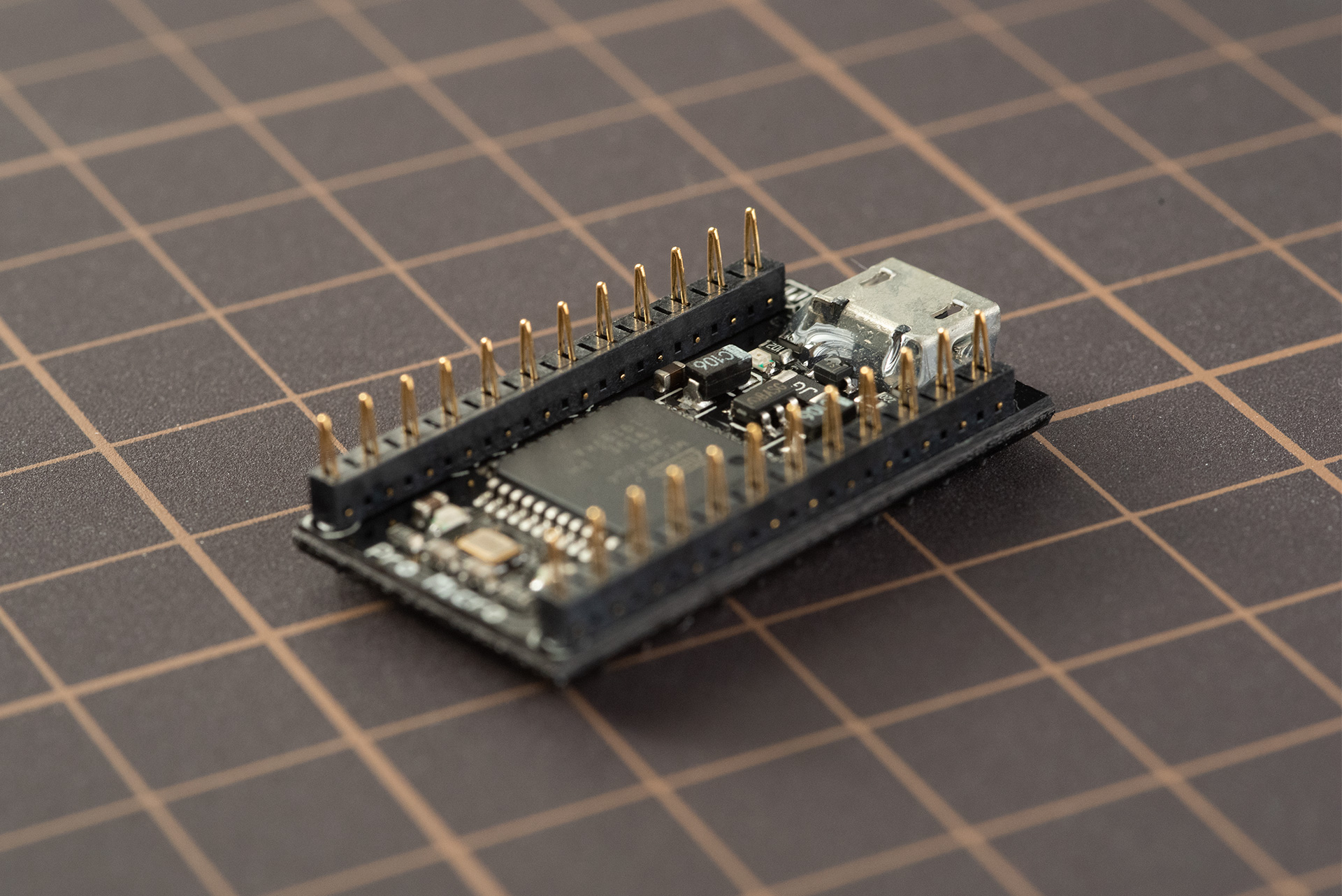
The controller is socketed onto the PCB with two Conthrough spring-pin headers so it can be removed later. Solder the two headers to the controller with the end whose holes sit closer to the pins inserted into the controller.
Before soldering, flash the controller while it's still easy to handle:
Controllers aren't included with our kits, so the firmware you need depends on the Pro Micro-compatible controller you chose when ordering (or sourced yourself). Download the Reviung 39 firmware for your controller from the firmware page, then flash it:
| Your controller | Firmware page tab | File | How to flash |
|---|---|---|---|
| Helios or SVLinky (RP2040) | Helios / Svlinky | .uf2 | Double-tap the reset button (or hold BOOT while plugging in). A drive called RPI-RP2 appears; drag the .uf2 onto it. |
| StemCell (STM32) | StemCell | .uf2 | Double-tap the reset button. A drive appears; drag the .uf2 onto it. Check the StemCell page for any jumpers your board needs. |
| Classic Pro Micro (ATmega32U4) | Pro Micro | .hex | Open the .hex in QMK Toolbox, tick Auto-Flash, then briefly short RST to GND (or press reset) to start flashing. |
Each controller has two firmware options:
- Default: standard QMK firmware with the keymap built in.
- VIAL: the same firmware, plus live key remapping in Vial without rebuilding anything.
Flash your controller before soldering it to the PCB, while it's still easy to handle. If it shows up as a drive (or flashes successfully in QMK Toolbox), it's working. If it doesn't, see Entering the Bootloader.
If your controller has a Micro-USB connector (like a classic Pro Micro), reinforce it with a little glue before you start. Micro-USB ports are prone to tearing off with repeated use.
2. Solder the Reset Switch
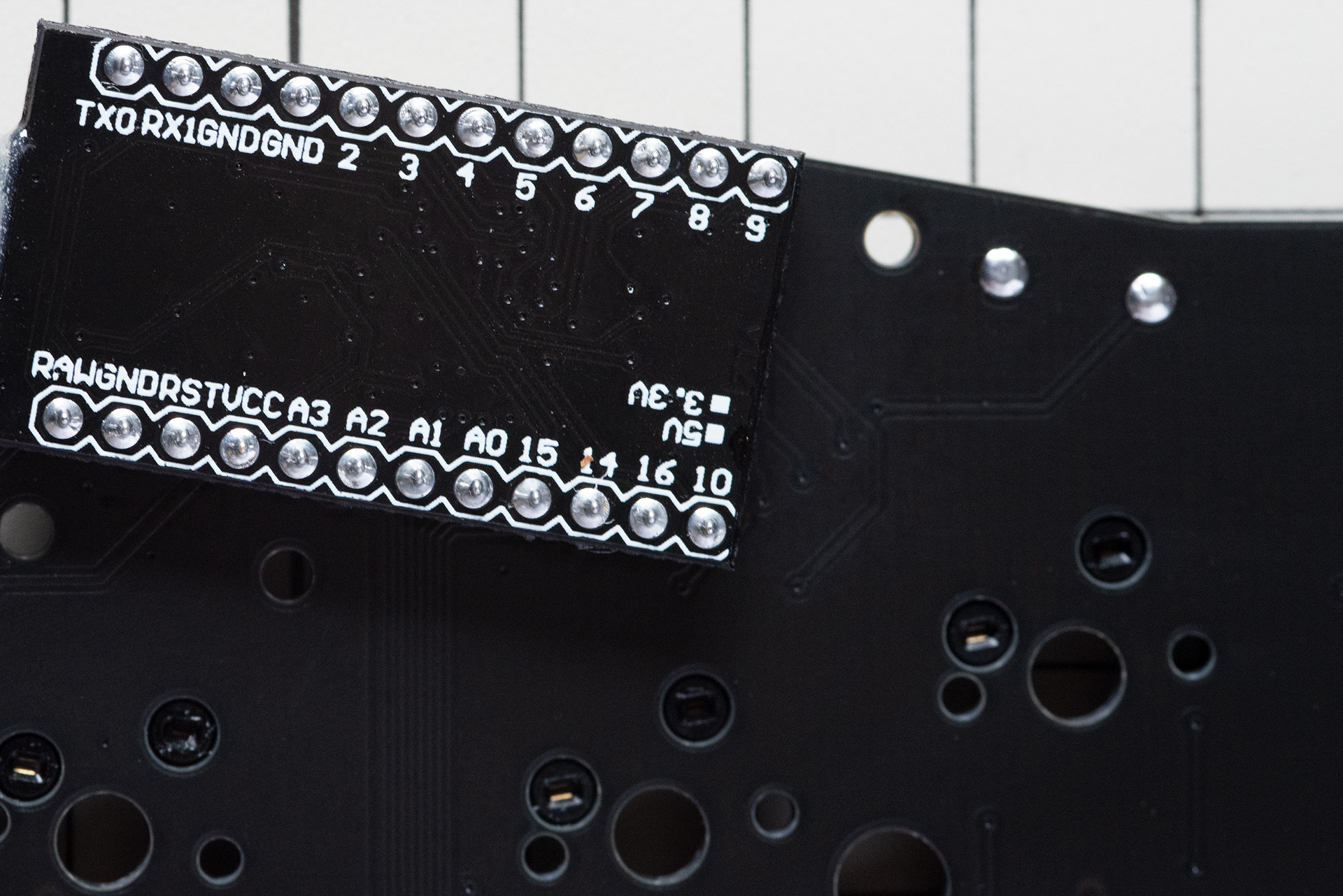
Solder the tactile reset switch to the back of the PCB, in the position
marked RESET.
3. Install the LEDs
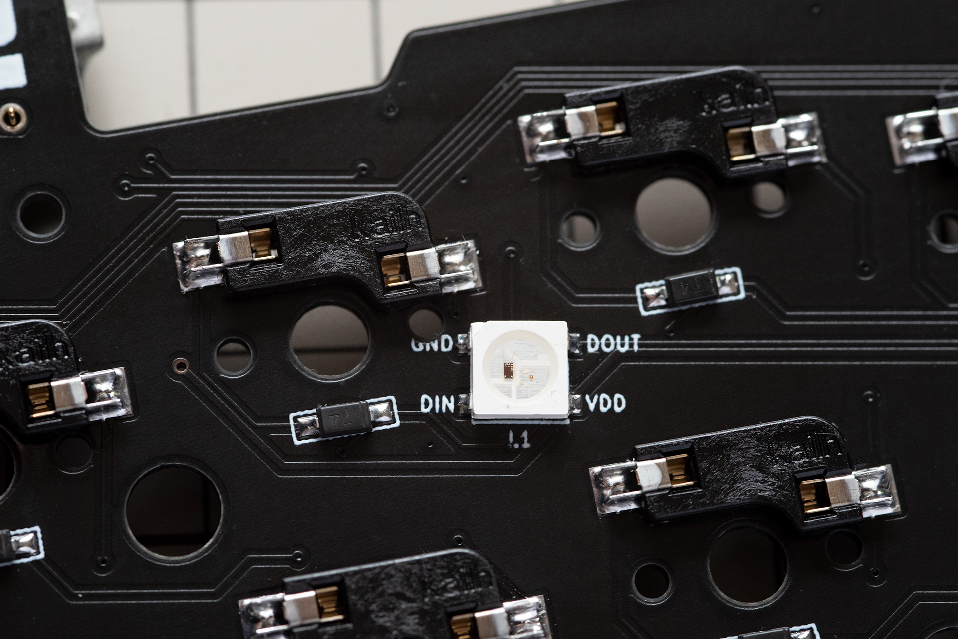
Install the 11 x WS2812B LEDs (10 rear-facing for underglow, 1 front-facing as an accent). Work through them in order and test each LED before moving on — the LEDs are wired in a chain, so one bad joint stops every LED after it from lighting.
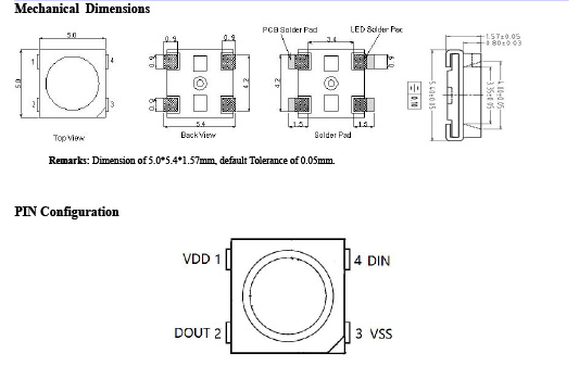
LEDs are orientation-sensitive. Align the notched (cut) corner of the LED with the marking on the PCB, and make sure the data-in arrow points the right way.
Use a temperature-controlled iron around 300°C. Apply flux, pre-tin one pad, seat the LED with tweezers and tack it in place, then solder the remaining pads. Clean the flux and test before continuing to the next LED.
The Mk-II's WS2812B LEDs are physically larger and more heat-tolerant than the SK6812MINI LEDs used on the original Reviung 39, which makes this step noticeably more forgiving.
4. Install the Diodes
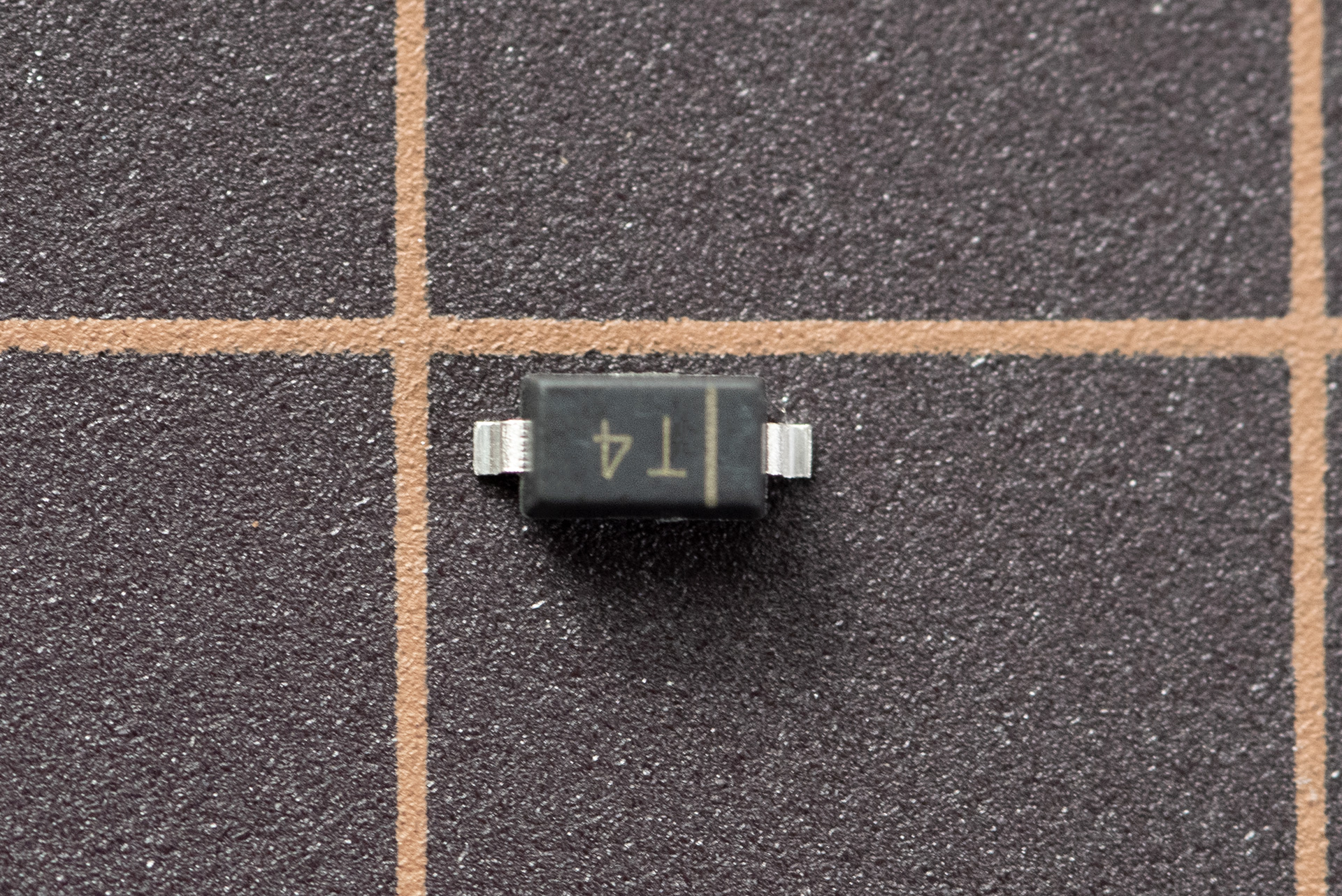
Install the 39 x 1N4148 SMD diodes.
Diodes are orientation-sensitive. The | mark on the diode must line up with
the | side of the ▷| marking on the PCB.
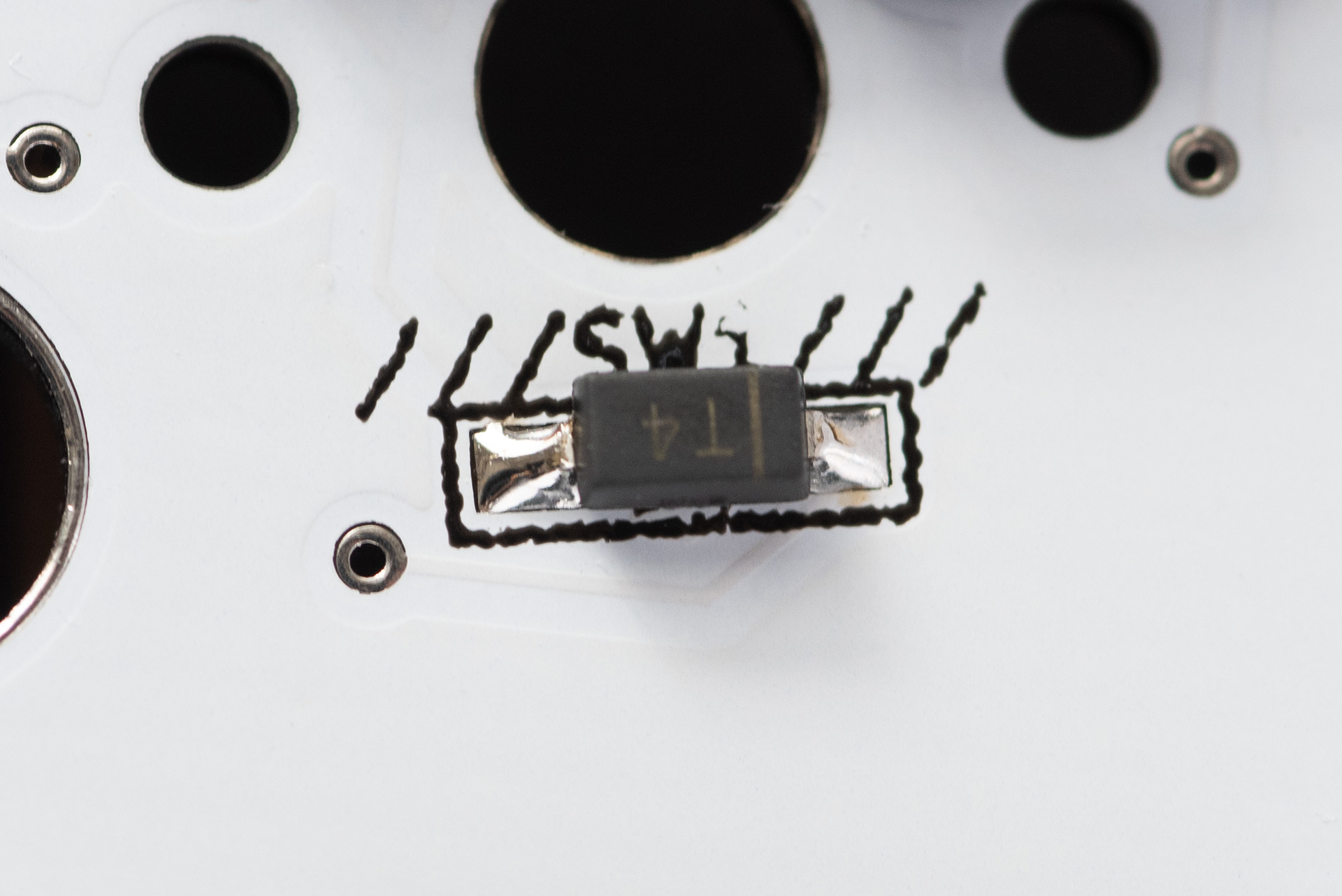
Apply flux to both pads, pre-tin one pad, place the diode with tweezers and re-flow to tack it down, then solder the opposite pad.
5. Install the Switch Sockets
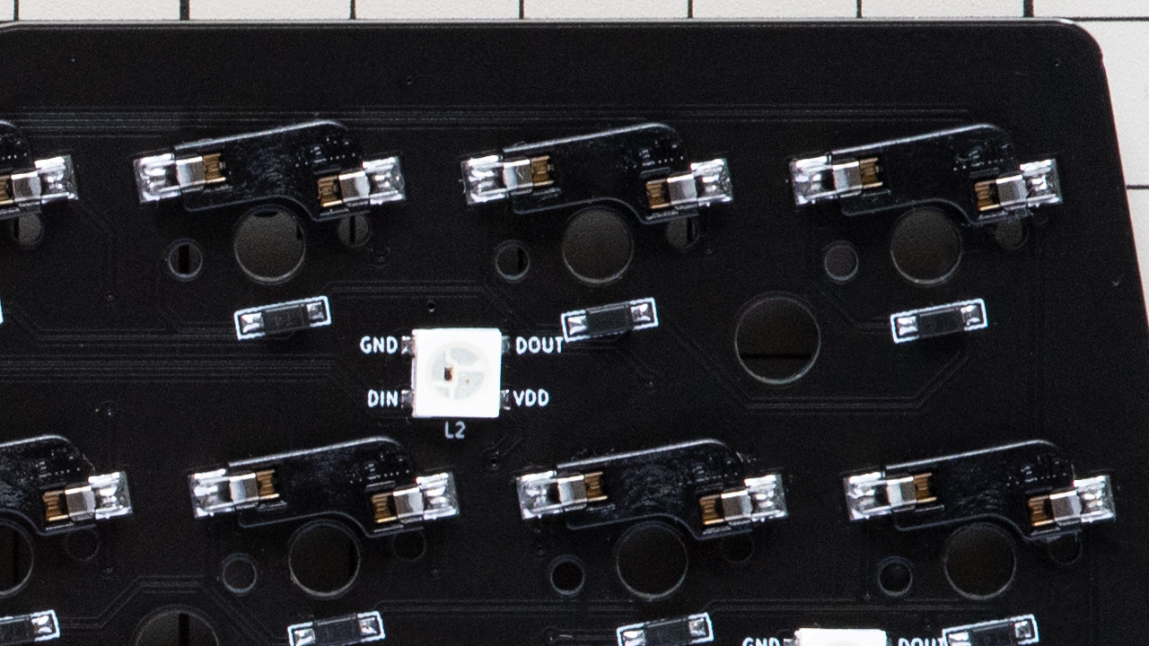
Solder the 39 x hotswap sockets to the back of the PCB.
The sockets fit only one way round. Make sure the open mouth of each socket faces outward and doesn't block the central switch hole.
Apply flux, heat the pad and socket together, feed a little solder into each of the two terminals, and hold the socket flat with tweezers as you remove the iron so it doesn't lift.
6. Mount the Stabiliser
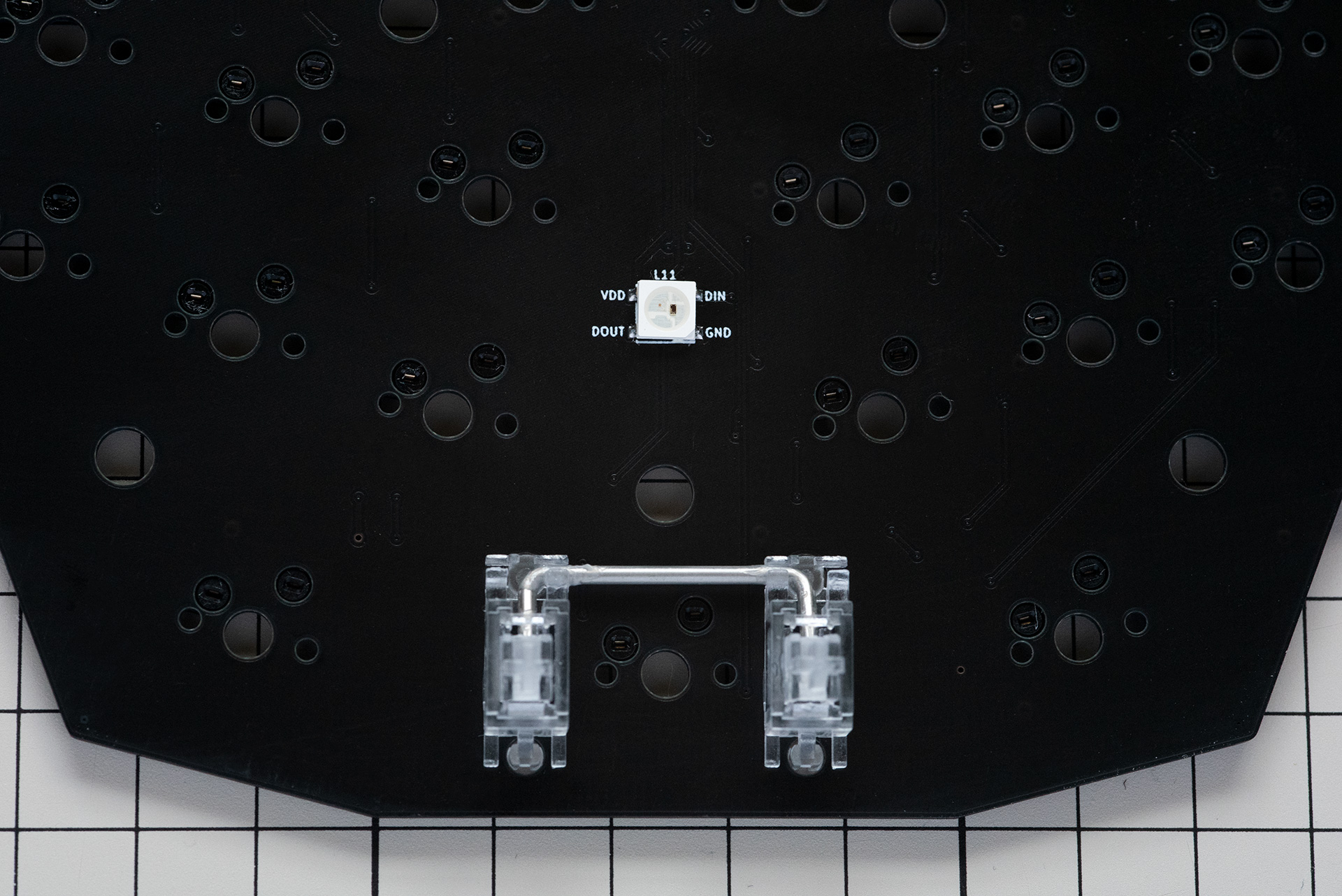
Fit the 2u stabiliser to the front of the PCB for the thumb-cluster space key, with the wire shaft facing up. Check from the side and rear that the clips are fully engaged.
7. Attach the Pro Micro Protection Cover
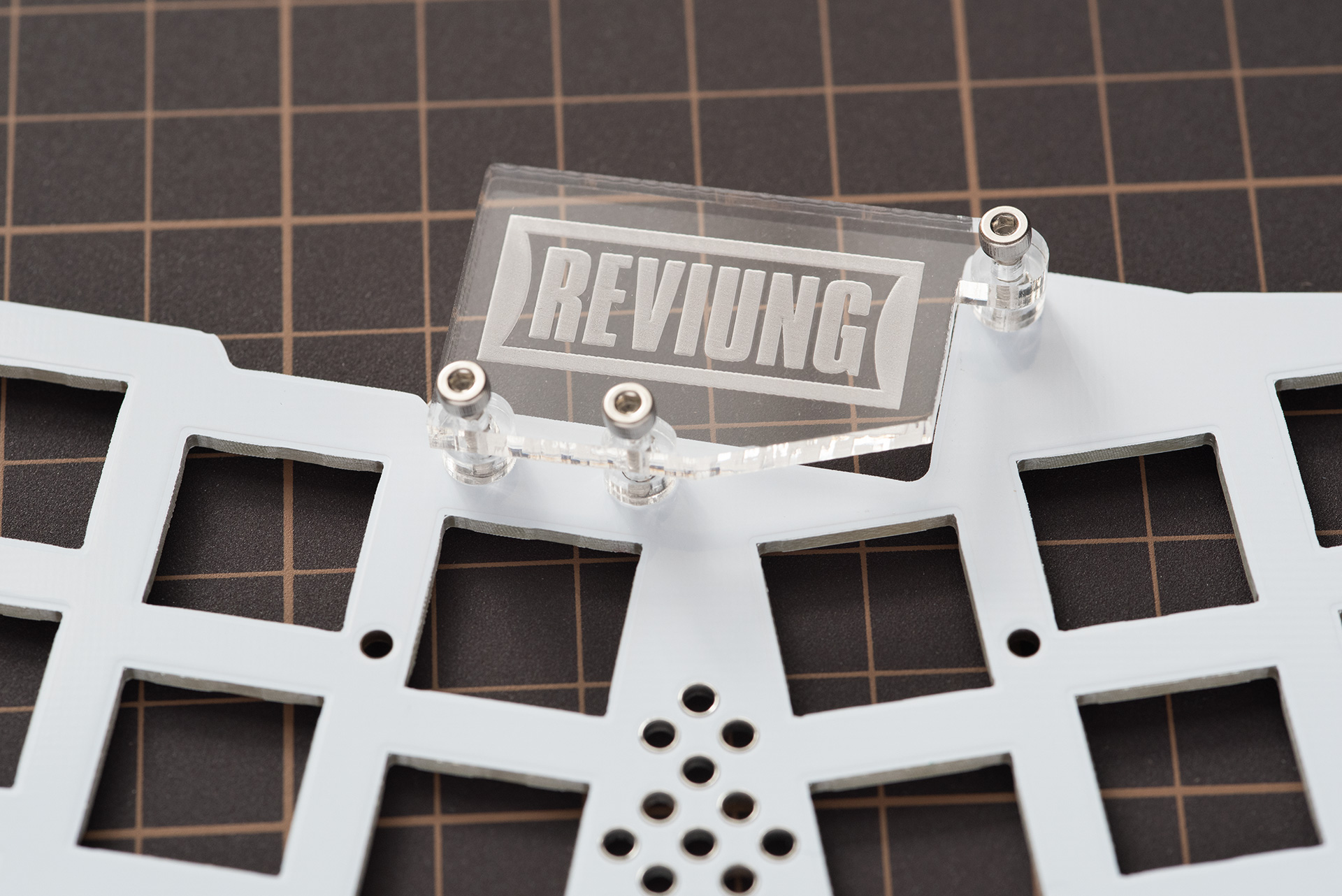
Attach the acrylic Pro Micro protection cover to the top plate using the spacers and screws. Peel the protective film off the acrylic parts first.
Do not overtighten the screws — acrylic parts can crack. Snug is enough.
8. Assemble the Plates
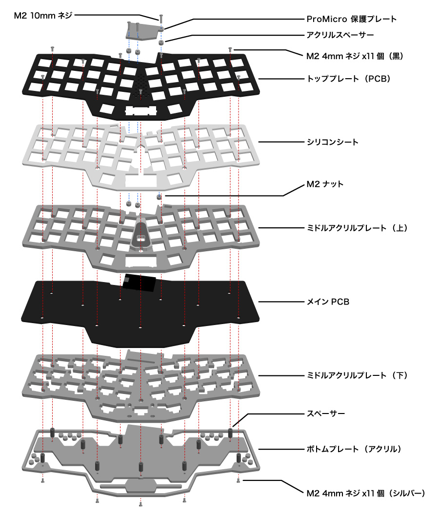
Build up the plate stack from the bottom:
- Fix the metal spacers to the bottom plate.
- Add the lower middle acrylic plate.
- Seat the main PCB.
- Add the upper middle acrylic plate, then the silicone sheet, then the top plate.
- Tighten the screws down from the top-plate side.
- Stick the rubber feet to the four corners and the centre of the bottom plate.
9. Install the Switches
Push your 39 MX switches down through the top plate and into the hotswap sockets below. Check that each switch's pins are straight before pressing it home — a bent pin will fold under the switch instead of entering the socket.
10. Install the Keycaps
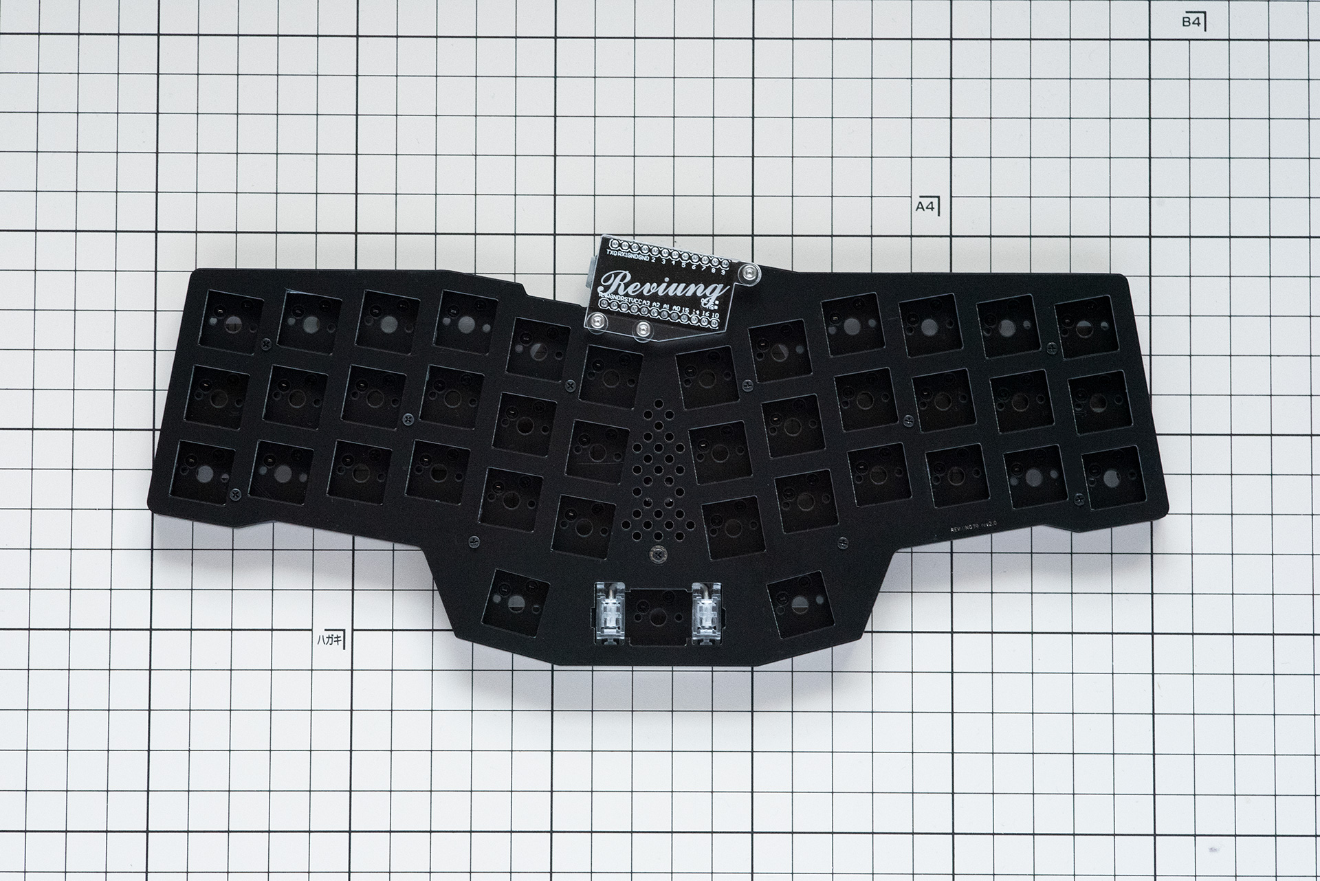
Fit your keycaps and you're all done! The thumb row can be laid out as
1.25U + 2.25U + 1.25U, or with 1U keys either side of the spacebar,
depending on your keycap set.