Build Steps
The Discipad is a through-hole kit, so we'll work from the lowest, flattest components up to the tallest. Insert each component from the top of the PCB, fold the legs out slightly to hold it in place, solder from the underside and then clip the excess legs flush.
Have no-clean flux paste and solder wick on hand before you start. They are not strictly required, but they make the USB Type-C port (Step 4) far easier and let you clear any solder bridges.
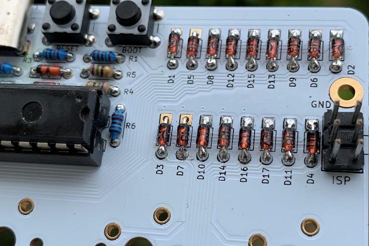
1. Install Diodes
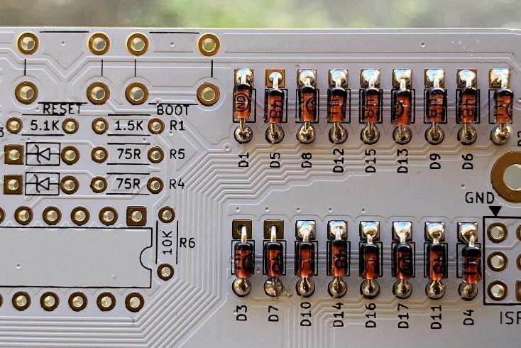
Install the 17 x 1N4148 diodes.
This part has a specific orientation. The black bar on the diode points upward and lines up with the square pad on the silkscreen.
Place the diodes, folding down the legs to hold them in place as you go. Solder and clip the legs.
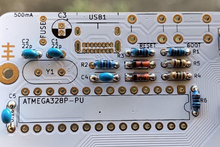
2. Install Resistors
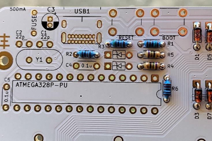
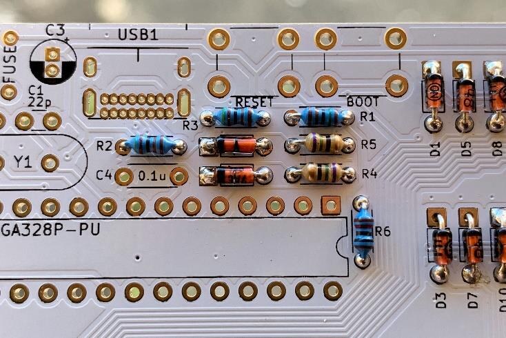
Install the resistors: 1 x 10K, 2 x 5.1K, 1 x 1.5K and 2 x 75R.
Resistors do not have a specific orientation.
Insert and solder using the same method you used in Step 1.
3. Install Zener Diodes
Install the 2 x 3.6V Zener diodes.
This part has a specific orientation. The black bar on the diode points to the left and lines up with the square pad.
These two diodes are kept separate from your other diodes — they are not interchangeable. Use the same soldering method.
4. Install USB Type-C Port
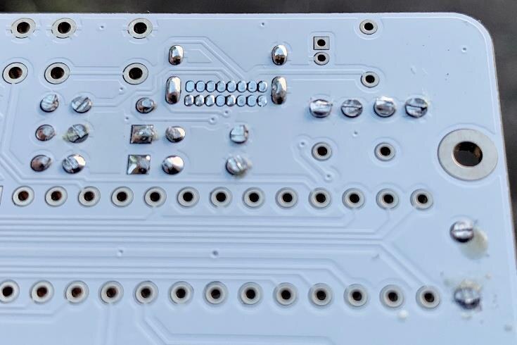
Install the USB Type-C port. Insert it and flip the board over. Use a small piece of tape to hold it if you have trouble keeping it in place. Solder only one of the bottom legs first, remove the tape, then reheat that pad and press down to ensure the port sits flush and even before soldering the other three legs.
The small data/power pins use a different technique to the rest of the components. If you have no-clean flux available, apply it across the pins now. Apply a small amount of solder and drag your iron across the pins, repeating until all the holes are filled. Use solder wick to clear any bridges.
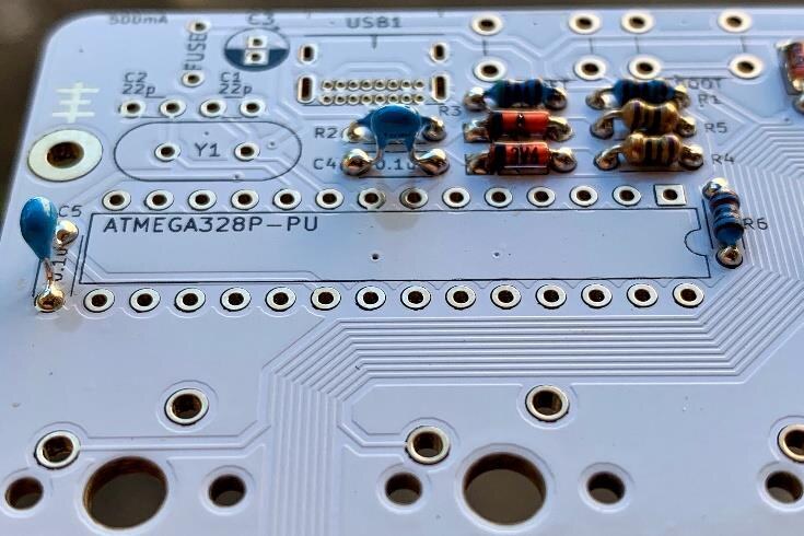
5. Install 0.1uF Capacitors
Install the 2 x 0.1uF capacitors. These are the larger blue capacitors with the wider, winged legs.
No specific orientation.
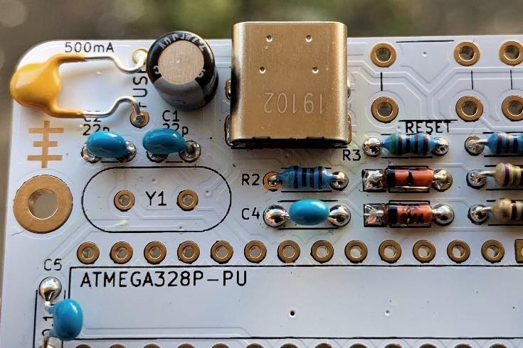
6. Install 22pF Capacitors
Install the 2 x 22pF capacitors. These are the smaller blue capacitors with straight legs.
No specific orientation.
7. Install 4.7uF Capacitor
Install the 1 x 4.7uF capacitor.
This part has a specific orientation. The longer leg goes to the square pad and the white mark points upward.
8. Install Resettable Fuse
Solder the resettable fuse and fold it down as pictured.
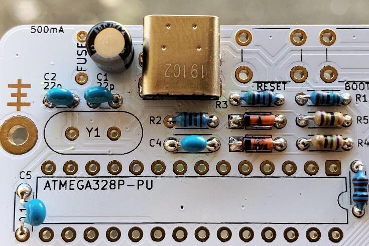
9. Install Crystal
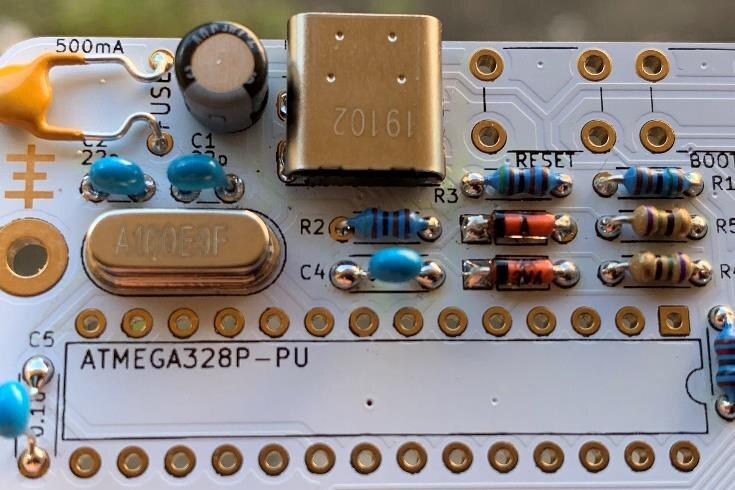
Install the 1 x 16MHz crystal.
No specific orientation.
10. Install Pushbuttons
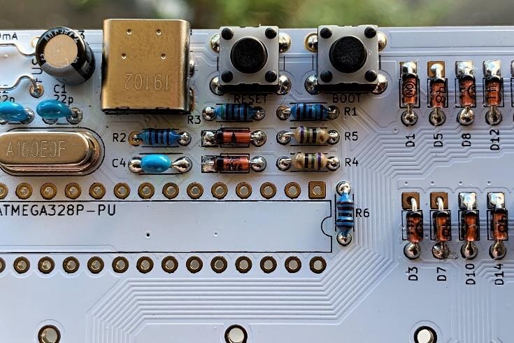
Install and solder the 2 x 6mm pushbuttons (the BOOT and RESET switches).
No specific orientation.
11. Install IC Socket & Microcontroller
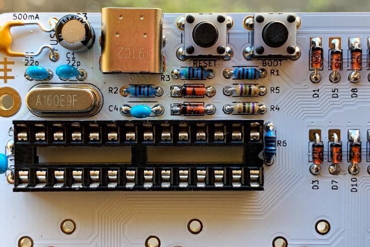
Install the 28-pin IC socket and the ATmega328p microcontroller.
Take note of the notches marked on the PCB, the socket and the microcontroller for the correct orientation. Do not insert the microcontroller before soldering the socket to the PCB.
Solder two opposite corners of the IC socket. Reheat each and press down to ensure the socket is flush with the PCB, then solder the rest of the pins.
Insert the microcontroller into the socket with the notch on the right side. You may have to gently bend the pins slightly inward for proper alignment.
On a white PCB, leftover flux may be very visible after soldering. This is fine and will be hidden, but if you'd like to clean it, rub the soldered area with a lint-free cloth and isopropyl alcohol, then wipe dry.
12. Install Header
Install the 1 x 6-pin header with the longer side of the header on top.
Solder only one pin first, then heat that pin and press down to align the header flush with the PCB before soldering the rest. Use a rag or glove to protect your hand from the heat.
13. Install Standoffs
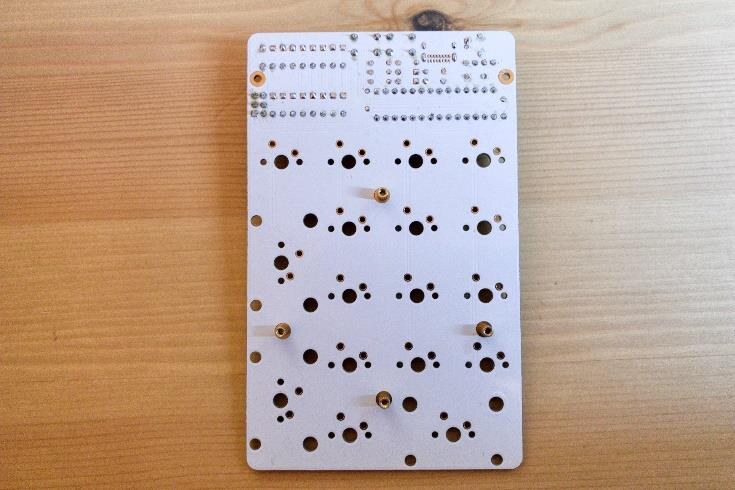
Using the 4 x M2 4mm screws, install the 4 x M2 5mm standoffs to the bottom of the PCB.
Fit the standoffs before soldering the switches.
14. Install Stabilisers & Switches
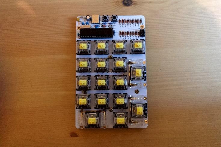
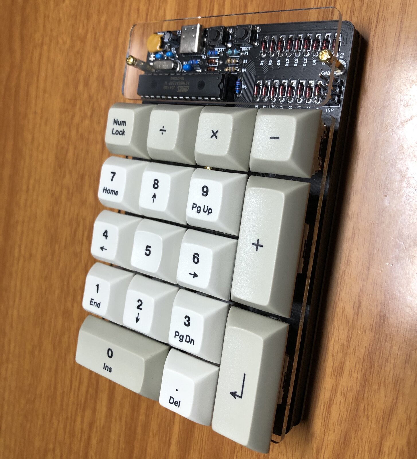
Screw in the 3 x 2u stabilisers, then install and solder your 17 switches.
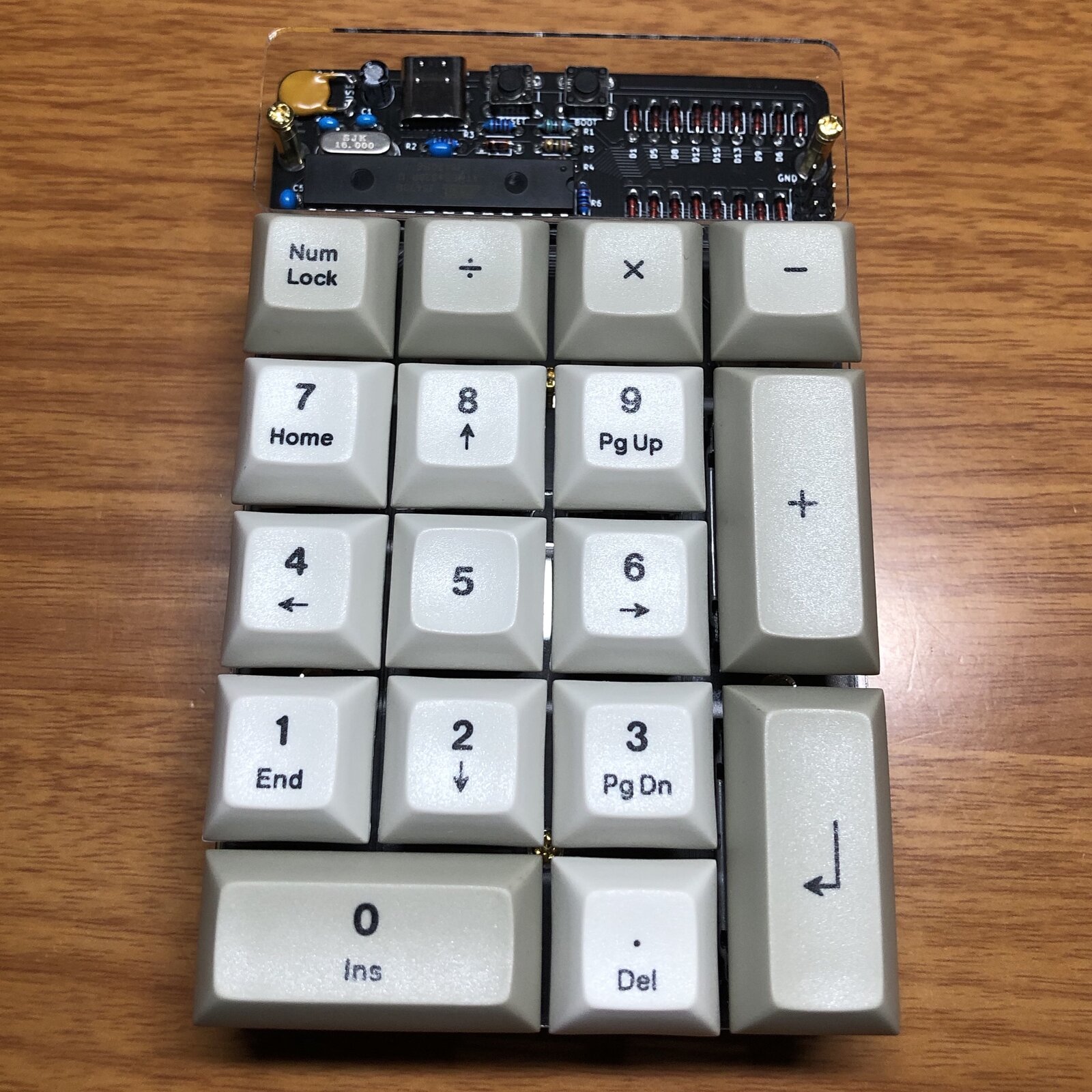
Add your keycaps and you're all done!